
Every operating plant is the product of four orthogonal decisions — energy reuse, process configuration, supersaturation method and crystal growth configuration. This page separates them on purpose, because conflating them is the most common cause of mis-selection.
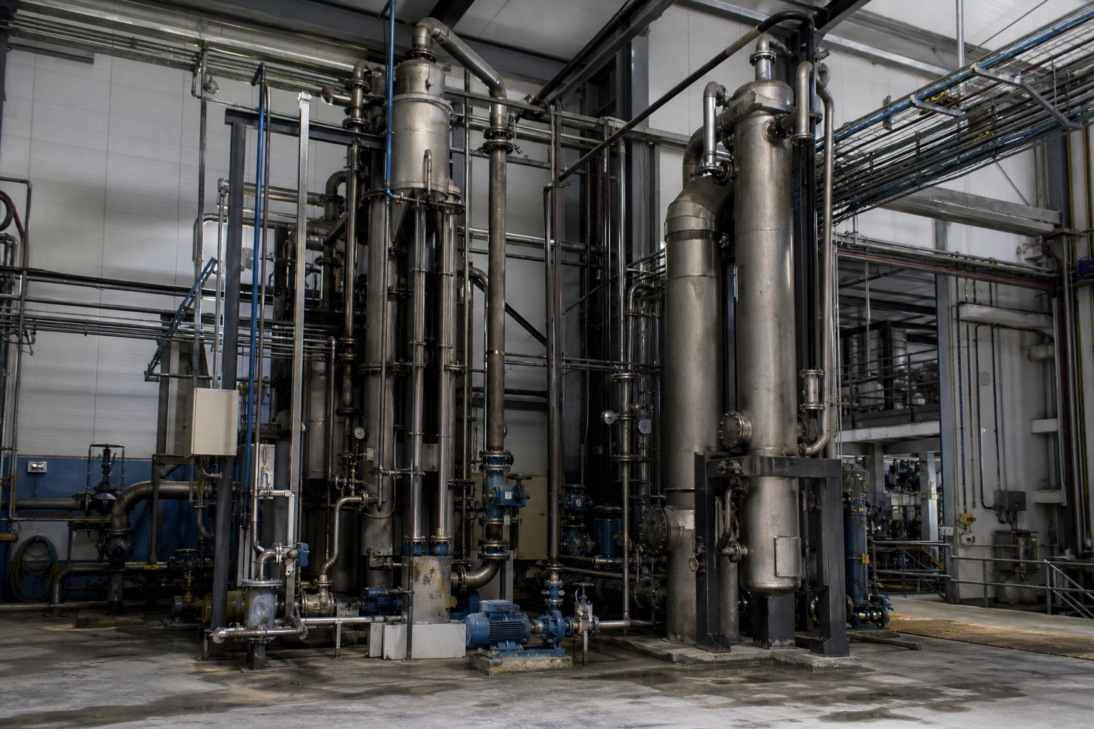
A complete evaporation–crystallization plant makes exactly one choice in each dimension below. They are independent engineering decisions that combine — never a list of alternatives to pick a single winner from.
How the latent heat of evaporated vapor is recovered — MVR (mechanical recompression), multi-effect (cascade reuse) or TVR (thermal ejector). Sets operating cost and carbon intensity.
How feed liquid contacts the heat transfer surface — falling film, forced-circulation, rising film or vacuum/low-temperature operation. Sets fouling resistance and residence time.
How the mother liquor is driven into the supersaturated state — evaporative, cooling, vacuum cooling, reaction or evaporation–cooling hybrid. Decided by the solubility curve of your salt.
How crystals are nucleated, grown and classified inside the vessel — forced-circulation (FC), DTB (draft tube baffle), Oslo (fluidized bed) or agitated. Sets crystal size, purity and downstream separability.
The working principles, operating ranges and honest trade-offs behind every option — with the applicability conditions of each number stated explicitly.
A mechanical compressor (centrifugal or roots type) raises the pressure and saturation temperature of the evaporated vapor so it can serve as the heating steam for the same effect. MVR is electrically driven, achieves specific energy consumption of 15–25 kWh per tonne of water evaporated, and is the default choice for new plants where grid capacity and power price are favorable. No live steam consumption in steady-state operation; small amount of motive steam only for start-up.
Vapor boiled off in effect i becomes the heating steam for effect i+1, which operates at lower pressure and temperature. Steam economy scales roughly with the number of effects — a 3-effect evaporator typically consumes 0.25–0.40 tonnes of live steam per tonne of water evaporated (a single-effect consumes ~1.0). Lower upfront cost than MVR, higher steam consumption — favored where low-pressure steam is already available on site.
A steam ejector uses high-pressure motive steam (typically ≥8 bar(g)) to entrain and recompress part of the process vapor to a usable pressure. Specific steam consumption around 0.3–0.5 tonnes motive steam per tonne of vapor reused. Medium CapEx and OpEx; useful when high-pressure steam is already available and electrical supply is unreliable. Frequently combined with multi-effect as a booster on the first effect.
Liquid is distributed over the top of vertical tubes and falls as a thin film under gravity, with vaporization at the film surface. Highest heat transfer coefficient (typically 1,500–3,000 W/m²·K), short residence time (a few seconds). The standard choice for clean, low-viscosity, heat-sensitive feeds — fermentation broth, sugar juice, dairy, caustic recovery. Sensitive to fouling and uneven distribution at high viscosity.
An external circulation pump pushes liquid through the heat exchanger at high velocity (typically 2–3 m/s tube-side), suppressing boundary-layer boiling and scale deposition. Higher pumping energy than falling film, but the standard choice for high-TDS, scaling-prone, high-viscosity and crystallizing feeds where falling film would foul within hours. Temperature rise across the heater kept low (typically ≤10 °C) to prevent wall boiling.
Vapor lift pushes liquid upward through vertical tubes. Tolerant of moderate viscosity and foaming-prone streams. Less common in new plants than falling film and forced-circulation, but useful in specific retrofit or specialty applications where the feed contains suspended solids that would block a falling-film distributor.
Evaporation under reduced pressure (typically 60–90 °C boiling), used for heat-sensitive products (enzymes, plant extracts, certain food juices) and to enable recovery of low-grade waste heat. Often paired with heat-pump cycles. Not a separate heat-transfer regime in itself — combines with falling-film or forced-circulation above.
Concentration by water removal drives supersaturation. The default route for salts whose solubility is weakly dependent on temperature — NaCl, Na₂SO₄, (NH₄)₂SO₄, ammonium chloride, mixed salts in ZLD brines. Typically combined with forced-circulation to manage the scaling and fouling that accompanies high supersaturation.
Temperature reduction drives supersaturation for salts whose solubility drops steeply with temperature — adipic acid, boric acid, potassium nitrate, PTA, xylitol. Heat is removed via a cooling surface (jacket, coil or external exchanger). Temperature differential across the cooling surface kept low (≤5–8 °C per stage) to avoid nucleation bursts.
Adiabatic flash cooling under vacuum — the mother liquor is introduced into a vessel at reduced pressure; part of the water evaporates, taking its latent heat from the bulk and cooling it rapidly. No cooling surface to foul. Standard for thermal-sensitive bio-products — lysine, MSG, citric acid, amino acids — and for streams where wall cooling would cause incrustation.
Evaporative concentration brings the liquor close to saturation, then cooling completes crystallization. Used when a single method under-performs on yield, energy efficiency or PSD — e.g., when the solubility curve is moderately temperature-sensitive but evaporation alone would leave yield on the table.
Two reagents combine to form a sparingly soluble salt that precipitates directly — Li₂SO₄ + Na₂CO₃ → Li₂CO₃↓; iron phosphate from Fe/PO₄ sources. Supersaturation is generated by the reaction itself. PSD control demands tight reagent stoichiometry, mixing control and often a downstream agitated or DTB growth vessel.
Engineering reliability first; medium crystals 0.2–0.8 mm; tolerates high-TDS, scaling and fouling. The workhorse for ZLD mixed-salt service and difficult liquors.
Product quality first; large crystals 0.5–2 mm with narrow PSD via classified-fines removal. Preferred for fertilizers, organic salts and large continuous plants.
Crystal quality first; largest crystals 1–5 mm, very low fines, suited to high-purity metal salts — battery-grade NiSO₄ / CoSO₄ / MnSO₄. Supersaturation tolerance is low (≤1–2 g/L to avoid spontaneous nucleation).
Batch operation, reaction crystallization and specialty products — configured case-by-case around stoichiometry, mixing and wash requirements.
All figures above are indicative ranges under typical operating conditions — actual performance depends on feed, ΔT, compressor type and integration scope. See the dedicated Compare Technologies page for side-by-side decision tables.
A static routing aid — find your entry point in each dimension, and the combination becomes your candidate process route for preliminary screening.
One choice in each dimension combines into a single coherent process route — e.g., MVR + Forced-Circulation + Evaporative + FC for a high-TDS ZLD train, or Multi-Effect + Falling Film + Reaction + DTB for battery-grade Li₂CO₃.
All listed routes are for preliminary screening only. Final process selection requires solubility data, impurity profiling, crystallization trials and project-specific engineering evaluation.
First-pass orientation only — which configurations are typically deployed in which industries. Shading indicates typical deployments, not mandatory ones.
| Industry | Falling Film | Forced-Circ. | MVR | Multi-Effect | FC Cryst. | DTB Cryst. | Oslo Cryst. | Vacuum Cool |
|---|---|---|---|---|---|---|---|---|
| Chemical & Agro | ||||||||
| Battery Materials | ||||||||
| Coal Chemical | ||||||||
| Food & Fermentation | ||||||||
| Complex Wastewater |
Matrix shows typical (not mandatory) configurations. Final selection requires project-specific evaluation against documented feed and product targets.
Below the abstract matrix sits a concrete view: which chemical systems map to which configuration in each industry. This is what the dot matrix above is summarizing.
| Industry | Forced-Circulation | DTB | Oslo | Cooling / Vacuum Cooling |
|---|---|---|---|---|
| Battery Materials & Hydrometallurgy | Li-ion by-product Na₂SO₄ wastewater ZLD; LiOH concentration | Battery-grade Li₂CO₃ continuous crystallization | High-purity NiSO₄ / CoSO₄ / MnSO₄ large crystals | Battery-grade LiOH·H₂O (corrosive, steep solubility) |
| Chemical & Agrochemical | High-COD pesticide wastewater ZLD; mixed salt separation | Co-production of large-granule (NH₄)₂SO₄ fertilizer | High-purity agrochemical active ingredients | Adipic acid (solubility strongly temperature-dependent) |
| Food, Fermentation & Bioprocessing | Fermentation broth pre-concentration | — | — | Lysine / MSG / citric acid (thermal-sensitive) |
| Coal Chemical & Mining | Coal-chemical wastewater ZLD; NaCl/Na₂SO₄ salt splitting | — | — | — |
| Complex Industrial Wastewater | High-TDS / high-COD / heavy-metal-bearing effluent ZLD | — | — | — |
Application examples reflect systems EvapCryst and its partner network have actually engineered or rebuilt. The matrix is not exhaustive — every chemical system with documented solubility data can be evaluated. For systems outside this table, send us the feed composition and we will screen the applicable routes.
The most common decision points, distilled. All values are indicative ranges for new-build plants under typical operating conditions; actual performance depends on feed, ΔT, compressor type and integration scope.
| Parameter | MVR | Multi-Effect | TVR |
|---|---|---|---|
| Energy Source | Electricity (compressor) | Low-pressure live steam | High-pressure motive steam + process vapor |
| Specific Energy Consumption | 15–25 kWh / tonne water evaporated | 0.25–0.40 t steam / tonne water (3-effect) | 0.30–0.50 t motive steam / tonne water |
| CapEx | Higher | Lower | Medium |
| OpEx (energy) | Low | Higher (steam) | Medium |
| Number of Effects | Single-effect with vapor reuse | 2–5 effects typical | Single + ejector (often 1st-effect booster) |
| Best For | Large new plants; electricity available; decarbonization priority | Sites with abundant low-pressure steam | Hybrid with multi-effect; cheap motive steam; unstable grid |
| Limitation | Compressor maintenance; electrical capacity; higher CapEx | Higher steam & cooling-water consumption; larger footprint | Limited compression ratio (typically ≤1.5×); motive steam dependency |
| Parameter | Forced-Circulation (FC) | DTB (Draft Tube Baffle) | Oslo (Fluidized-Bed) |
|---|---|---|---|
| Selection Priority | Engineering reliability | Product quality (narrow PSD) | Crystal quality (large, pure) |
| Typical Crystal Size | 0.2–0.8 mm | 0.5–2 mm | 1–5 mm |
| PSD Width | Wide | Narrow (classified-fines removal) | Very narrow (fluidized classification) |
| Supersaturation Tolerance | High (recirculation dilutes) | Medium (controlled by draft-tube velocity) | Low (≤1–2 g/L to avoid spontaneous nucleation) |
| Best For | High-TDS, scaling, fouling, mixed salts | Fertilizers, organic salts, large continuous plants | High-purity metal salts; battery-grade sulfates |
| Typical Products | NaCl, Na₂SO₄, ZLD mixed salts | (NH₄)₂SO₄, KCl, urea, lysine | Battery-grade NiSO₄ / CoSO₄; high-purity agrochemicals |
| Scaling Resistance | Excellent | Good | Moderate (sensitive to feed stability) |
| Crystal Size Control | Limited (no internal classification) | Strong (classified-fines removal loop) | Excellent (fluidized-bed classification) |
| Residence Time | Medium (hours) | Medium (hours) | Long (tens of hours) |
The four technology dimensions above are realized through seven equipment modules. Some are manufactured in-house; others are integrated from qualified partners. The labeling is honest — engineering responsibility is never outsourced, but manufacturing scope is.
Falling film, forced-circulation and rising film evaporators. Heat transfer area from 10 m² to >1,000 m², delivered standalone or as the front end of a crystallization train.
Forced-Circulation, DTB, Oslo, agitated and custom configurations. Process-specific design based on solubility data, target PSD and impurity profile.
Centrifugal and roots MVR compressors for vapor recompression duty, sized to specific ΔT and vapor volume.
Shell-and-tube, plate and custom vapor–liquid separators. Material-specific fabrication (SS316L, duplex, titanium, Hastelloy).
Liquid-ring pumps, steam ejectors, surface and mixing condensers — sized for the vacuum level and non-condensable load of the process.
Pusher, peeler and basket centrifuges; belt, drum and pressure filters. Selected by crystal morphology, mother-liquor viscosity and washing requirement.
PLC/SCADA, process analytics, instrumentation and remote monitoring — including density, turbidity, PSD and supersaturation loops where applicable.
Where partner-supported equipment is used, it is identified as such and qualified by EvapCryst engineering. See how modules combine into complete plants on the Solutions pages.
The questions our process engineers answer most often — starting with the single most common sourcing error.
They coexist. MVR is an energy reuse strategy (Dimension A); forced-circulation is a process configuration (Dimension B); FC is a crystal growth configuration (Dimension D). A single high-TDS wastewater ZLD plant is typically MVR-driven, uses forced-circulation in the evaporator body, and an FC crystallizer for the final supersaturation step. They are answers to four different engineering questions, not four competing equipment choices. Reading them as alternatives is the most common sourcing error we see in incoming inquiries.
DTB offers narrow PSD (0.5–2 mm) with classified-fines removal — preferred when downstream centrifugation throughput is the priority. Oslo fluidized-bed produces larger crystals (1–5 mm) with very low fines — preferred when crystal purity and large particle size matter most (battery-grade NiSO₄/CoSO₄, high-purity agrochemicals). Both can produce high-purity product; the choice depends on which downstream property — centrifuge yield or crystal size — is more valuable to your plant.
Evaporative crystallization drives supersaturation by removing water — concentration rises, and the salt crosses its solubility line. Vacuum cooling drives supersaturation by lowering temperature — solubility drops — via adiabatic flash under vacuum, with the flashed vapor condensed externally. For flat-solubility salts (NaCl, Na₂SO₄) only evaporative works. For steeply-rising solubility curves (amino acids, citric acid, adipic acid) vacuum cooling is far more efficient. Both are supersaturation methods (Dimension C) — they can be combined with FC, DTB or Oslo on Dimension D.
TVR wins when high-pressure motive steam (≥8 bar(g)) is already available on site — for example, from a backpressure turbine exhaust — electricity is unreliable or expensive, and the compression ratio required is modest (typically ≤1.5×). MVR wins when steam is expensive, electricity is cheap and stable, or decarbonization is a project driver. Many existing plants run a hybrid: multi-effect with a TVR booster on the first effect. For greenfield sites with grid power, MVR is now the default.
MVR needs stable electrical capacity at the compressor rating (typically 200 kW to >2 MW for industrial-scale plants) at 400 V or 690 V 3-phase, plus a small amount of start-up steam. Multi-effect needs low-pressure steam (typically 4–10 bar(g)) at a rate of 0.25–0.40 t per tonne of water evaporated, plus cooling water for the final-effect condenser. TVR needs high-pressure motive steam (≥8 bar(g)). Cooling water at 25–32 °C is required for condensation in all three routes.
Send us the feed composition, throughput, target product specification and site utilities. Our process engineers will screen the four dimensions against your requirements and return an indicative technology route — not a brochure.
Send your feed characterization (TDS, COD, main salts, viscosity), throughput and product targets — we respond with a preliminary process route within two business days.