Textile & Dyeing

Engineered ZLD and resource recovery for textile and dyeing operations — high-COD, high-color, high-salt effluent with caustic recovery, dye recovery and mixed-salt separation opportunities.

Feed typically presents COD 1,000–15,000 mg/L, color >1,000 Pt-Co and NaCl / Na₂SO₄ at 1–8%, with 60–75% heat recovery available from 60–90°C effluent — targeting reusable-grade salt (Ca²⁺ / Mg²⁺ <10 mg/L, Fe³⁺ <5 mg/L).

Phase 2 — In Preparation · Content under development
industries textile
Process Challenges

What Makes Textile & Dyeing Wastewater Hard

Textile wastewater combines four of the most punishing characteristics for evaporation and crystallization systems. Solving them together — not in isolation — is what defines a workable route.

High COD & Refractory Organics

Dye molecules, auxiliaries, surfactants and sizing agents (PVA, starch) produce COD 1,000–15,000 mg/L — much of it biologically refractory (anthraquinone, azo chromophores). Direct crystallization yields colored, organic-contaminated salt; AOP + biological pre-treatment decides downstream salt quality.

High Color & Dye Residue

Residual reactive and disperse dyes (color >500–2,000 Pt-Co) carry through conventional treatment and stain the salt product. Color removal before evaporation (target <50 Pt-Co) is a product-quality decision, not just an aesthetic one — dyeing customers reject colored salt at >100 Pt-Co.

High Salt Loading (NaCl / Na₂SO₄)

Reactive dyeing uses 40–80 g/L NaCl or 20–40 g/L Na₂SO₄ as electrolyte; the salt is the dominant mass flow in the wastewater (5,000–80,000 mg/L TDS). Separating it into a reusable dyeing-grade product (Ca²⁺, Mg²⁺, Fe³⁺ each <5–10 mg/L) is the economic case for ZLD vs. paying $80–200/t for hazardous mixed-salt disposal.

Heat Recovery & Energy Cost

Dyeing effluent leaves the process at 60–90°C. Capturing this heat reduces evaporator steam duty materially; ignoring it makes MVR economics fail. Heat integration is not optional — it is the difference between viable and uneconomic operation.

Typical Applications

Four Application Areas in Dyeing & Finishing Mills

From compliance-driven dyeing effluent ZLD to caustic, salt and dye recovery — each application pairs a driver with its dominant technology route.

APPLICATION 01Compliance-Driven

Dyeing Wastewater ZLD

Compliance-driven minimization of dyeing effluent to zero liquid discharge — with condensate recovered for the next dyeing batch.

  • Pre-treatment: biological / advanced oxidation / adsorption
  • Membrane pre-concentration ahead of thermal duty
  • MVR evaporation + forced-circulation crystallization
  • Condensate reuse for the next dyeing batch
15–25 kWh/tMVR duty on textile brine service — or 0.25–0.40 t steam per tonne water on multi-effect; depends on feed TDS, boiling-point rise and utility prices
APPLICATION 02Recovery-Driven

Caustic Soda Recovery from Mercerizing

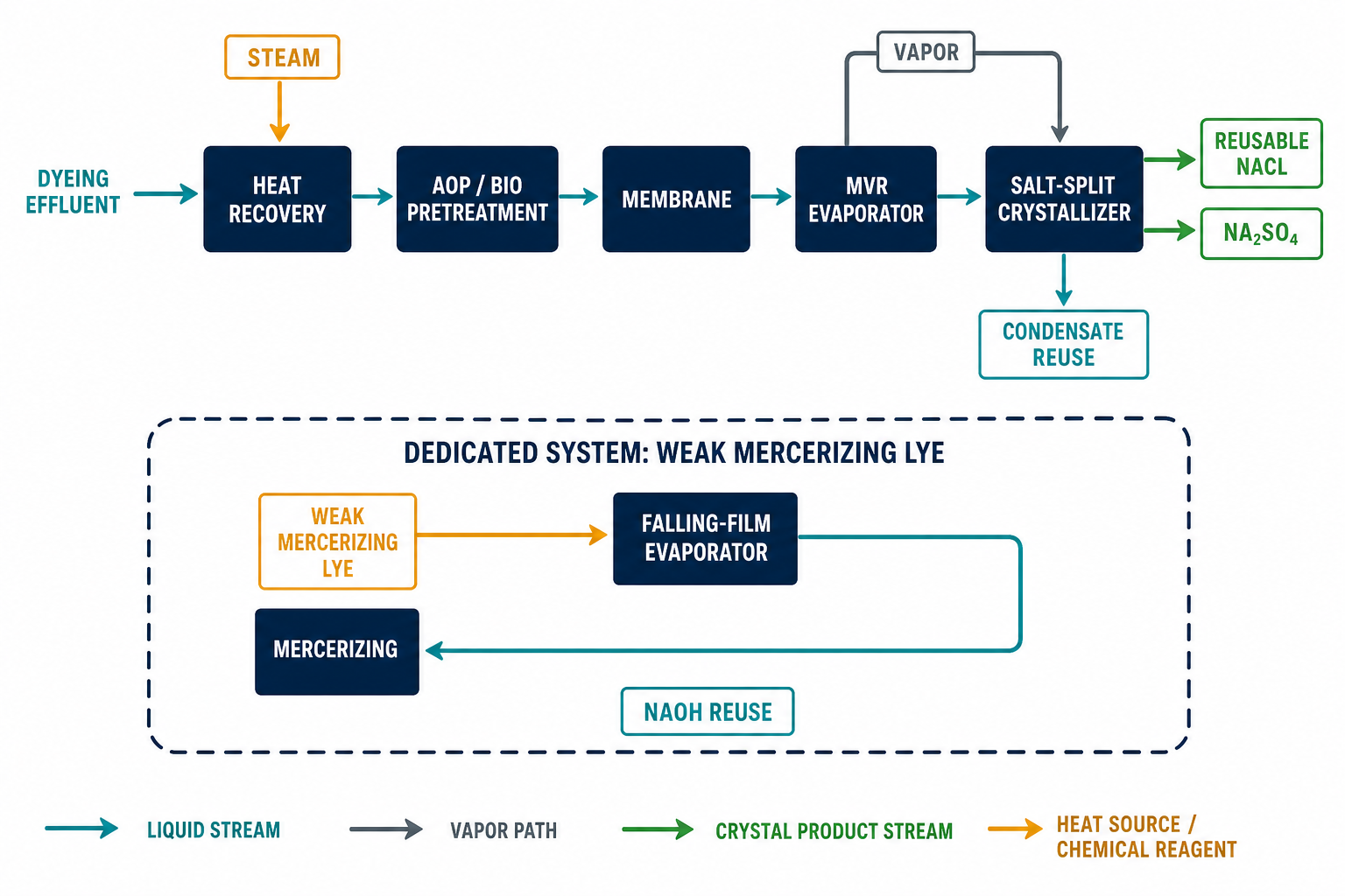
Weak mercerizing lye concentrated by falling-film evaporation and reused in the mercerizing loop — a dedicated system, never combined with the dyeing wastewater evaporator.

  • Weak lye concentration by falling-film evaporation
  • Reuse in the mercerizing loop
  • Strong alkalinity drives nickel-alloy material selection
  • Dedicated concentrator + vacuum cooler design
200–300 g/L NaOHmercerizing lye feed (viscosity 30–80 cP, BPE 15–30°C) — concentrated across the 280→450 g/L range in a dedicated falling-film system
APPLICATION 03Yield-Driven

Mixed-Salt Separation — NaCl vs Na₂SO₄

Selective crystallization driven by the dyeing salt composition, producing reuse-grade salt for the dyeing process.

  • Split-salt crystallization exploiting eutectic behavior
  • Reuse-grade salt for the dyeing process
  • FC / DTB crystallizer selection by service
  • Two salts, two separate reuse paths
NaCl >97%reuse-grade target with Ca²⁺ / Mg²⁺ / Fe³⁺ each <10 mg/L — co-crystallization at the ~17.5% Na₂SO₄ eutectic (100°C) must be avoided
APPLICATION 04Recovery-Driven

Dye Recovery — Selected Systems

Recovery of selected reactive / disperse dye systems, where concentration ahead of recovery and disciplined mother-liquor management make the loop work.

  • Selected reactive / disperse systems only
  • Concentration before recovery
  • Mother liquor management
Pre-Treatment Strategy

Pre-Treatment Decides Downstream Salt Quality

Selection depends on dye chemistry and the COD / TDS ratio. The sequence below is a screening frame — validated per stream, never assumed.

01

Biological Treatment

Anaerobic / aerobic stages for dye removal and breakdown of sizing agents, auxiliaries and surfactants — the biodegradable COD fraction.

02

Advanced Oxidation

Ozone / Fenton / UV attacks the refractory chromophores (anthraquinone, azo) that biology leaves behind.

03

Adsorption

Activated carbon / resin polishing for residual color and organics ahead of the evaporator.

04

Membrane Pre-Concentration

UF / NF / RO lifts the feed from ~1% to 5–8% TDS before thermal duty — shrinking the evaporator size.

Targets before evaporation: COD <500 mg/L and color <50 Pt-Co — product-quality limits for the recovered salt, not just aesthetic ones. Preliminary screening only; pre-treatment selection depends on dye chemistry and COD / TDS ratio.

Typical Process Route

Textile Dyeing Wastewater ZLD + Salt Recovery Route

Indicative process flow for reactive dyeing wastewater with high NaCl load, color and COD.

The canonical sequence: source heat recovery (60–90°C effluent → plate heat exchanger, 60–75% recovery) → biological / AOP pre-treatment (COD <500 mg/L, color <50 Pt-Co) → membrane pre-concentration (NF / RO, 1% → 5–8% TDS) → MVR (15–25 kWh per tonne water) or multi-effect (0.25–0.40 t steam per tonne water) evaporator → split-salt crystallization (NaCl vs Na₂SO₄, exploiting eutectic) → reusable-grade salt + condensate reuse.

Simplified PFD: Dyeing Effluent → Heat Recovery → AOP / Bio-pretreatment → Membrane Concentration → MVR Evaporator → Salt-Split Crystallizer → Reusable NaCl / Na₂SO₄ + Condensate Reuse

Simplified PFD for indicative routing only. Salt-splitting feasibility depends on the NaCl/Na₂SO₄ ratio, organic load and dye type. Reusable-grade salt claims require dyeing-loop validation with the customer’s dyeing process.

Technology Routes

Technology Options for This Industry

Preliminary screening only — the winning route is fixed by feed characterization, utility prices and the reuse target, never by default.

Membrane + MVR Hybrid

Low-energy ZLD: NF / RO pre-concentration (1% → 5–8% TDS) ahead of MVR evaporation at 15–25 kWh per tonne water — or multi-effect at 0.25–0.40 t steam per tonne water when steam is favored.

S1 · S4 →

Forced-Circulation Crystallization

Scaling- and fouling-dominant service — the default crystallizer choice where dyeing brines carry organics and hardness; applied after AOP + MVR concentration.

FC route →

Falling-Film Evaporation

Caustic recovery and cleaner streams — dedicated mercerizing lye concentrator across the 280→450 g/L range with nickel-alloy heating surfaces.

S3 route →

Selective Crystallization

Split-salt operation outside the eutectic band (~17.5% Na₂SO₄ at 100°C), exploiting metastable-zone differences to yield two salts with separate reuse paths. Feasibility is composition-dependent.

S2 route →

Salt purity and reuse-grade classification depend on residual organics and trace color. Mixed-salt separation feasibility requires laboratory phase-equilibrium test work. Routes shown are for preliminary screening only — reusable-grade salt for re-dyeing requires pilot validation on the customer’s dyeing process, and caustic recovery from mercerizing requires dedicated falling-film design with special alloy heating surfaces.

Stream Reference

Typical Chemicals & Stream Types

Common feed streams in textile dyeing and finishing mills, with the technology route typically considered for first-pass screening.

Chemical / StreamSource / ContextKey BehaviorTypical RouteMaterial Focus
STREAM 01Reactive dyeing wastewaterCotton reactive dyeing, high electrolyteNaCl 40–80 g/L; color 500–3,000 Pt-Co; COD 2,000–15,000 mg/LMembrane + MVR + SplitTitanium / Duplex
STREAM 02Disperse dyeing effluentPolyester disperse dyeing, carrier-basedCOD 1,500–8,000 mg/L; dispersants; lower saltAOP + MVR + FCDuplex 2205
STREAM 03Mercerizing lyeCotton mercerizing caustic bathNaOH 200–300 g/L; viscosity 30–80 cP; recoverableFalling Film RecoveryNi-200 / Special alloy
STREAM 04Printing rinse waterRotary / digital printing wash-offCOD 3,000–15,000 mg/L; pigment, binder, thickenerCoagulation + MVRDuplex 2205
STREAM 05Sizing / desizing wastewaterWarp sizing, PVA / starch removalBOD 2,000–10,000 mg/L; TDS <1,000 mg/LBio + Membrane316L
STREAM 06Salt recovered from dyeingCrystallized NaCl / Na₂SO₄ from ZLDTarget: NaCl >97%, Ca²⁺ / Mg²⁺ / Fe³⁺ each <10 mg/LFC / DTBTitanium (TA2)

Routes shown are for preliminary screening only. Reusable-grade salt for re-dyeing requires pilot validation on the customer’s dyeing process. Caustic recovery from mercerizing requires dedicated falling-film evaporator design with special alloy heating surfaces.

Material Selection

Materials by Stream Aggressiveness

Alkalinity, chloride and sulfate profiles — not habit — decide the metallurgy.

Stream ConditionRecommended MaterialEngineering Rationale
M1High-NaOH mercerizing streamsNickel 200 / special alloysCaustic stress-corrosion cracking attacks 316L at these concentrations; viscosity 30–80 cP and BPE 15–30°C drive dedicated falling-film design
M2Chloride-rich reactive dye brinesTitanium (TA2)Chloride profile drives selection — titanium on salt crystallization service (NaCl 40–80 g/L electrolyte streams)
M3Sulfate-rich streamsDuplex 2205Disperse dyeing effluent and printing rinse service with Na₂SO₄-dominant salt load
M4Mild combined effluent316LSizing / desizing streams at TDS <1,000 mg/L — low-corrosion service

Material selection follows the characterized feed — final choice is confirmed by corrosion coupon testing during bench & pilot validation.

Energy

Heat Recovery Integration

Dyeing effluent arrives hot — ignoring that heat makes MVR economics fail. Integration is not optional.

60–90°C dyeing effluent exit temperature from the dyeing vessel — exchanged against incoming fresh make-up water at 15–25°C
60–75% thermal energy recovered via plate heat exchanger (316L or titanium plates) — wide-gap plates with CIP capability, because dyeing effluent fouls aggressively
Hot effluent heat exchange with feed — reduces both evaporator steam duty and fresh-water heating load in one exchanger.
Condensate heat integration with site hot water — evaporator condensate carries usable heat back into the mill’s hot-water loop.
Steam economy optimization across multi-effect — evaluate MVR against multi-effect on electricity and steam prices before committing.
Project Library

Related Projects

We publish only what we can document — own deliveries and verified, anonymized references. Nothing else.

EvapCryst Own Deliveries

Project notes from our own textile & dyeing deliveries are being compiled for this page. Until documentation is complete, this slot stays intentionally empty — we do not list projects we cannot stand behind.

Anonymized Industry References

Public-domain and anonymized references for textile & dyeing ZLD and caustic recovery will be added after verification. We do not fabricate case data.

FAQ

Frequently Asked Questions

Can the recovered NaCl really be reused for reactive dyeing?+

Sometimes — it depends on the residual organic and trace-metal profile. Cotton reactive dyeing is sensitive to Ca²⁺, Mg²⁺, Fe³⁺ (each should be <5–10 mg/L) and residual organics (TOC <50 mg/L) that affect dye sorption and shade reproducibility. Reusable-grade salt is achievable in favorable cases after effective color / COD pre-treatment, but the salt must be validated by a dyeing trial on the customer’s fabric and recipe. We do not promise re-dyeing-grade salt without that validation.

Why is salt splitting (NaCl vs Na₂SO₄) necessary?+

Reactive dyeing effluent typically contains both Cl⁻ (from NaCl electrolyte) and SO₄²⁻ (from Na₂SO₄ electrolyte or reactive dye fixation). Their eutectic behavior and crystallization temperatures differ — at the NaCl-Na₂SO₄-H₂O eutectic (~17.5% Na₂SO₄ at 100°C) co-crystallization is unavoidable and produces contaminated salt of no reuse value. Selective crystallization outside the eutectic band, exploiting differences in metastable zones, can produce two separate salts each with a reuse path. Feasibility is composition-dependent.

How is heat recovered from dyeing effluent?+

Dyeing effluent exits the dyeing vessel at 60–90°C; incoming fresh water is at 15–25°C. A plate heat exchanger (typically 316L or Ti plates) transfers heat from outgoing effluent to incoming make-up water, recovering 60–75% of the thermal energy and reducing both evaporator steam duty and fresh-water heating load. The heat exchanger must be designed for fouling resistance (dyeing effluent fouls aggressively) — typically wide-gap plates with CIP capability.

Why is mercerizing caustic recovery treated separately?+

Mercerizing lye carries 200–300 g/L NaOH with viscosity 30–80 cP and BPE 15–30°C — concentrations that aggressively attack 316L by caustic SCC and require Nickel 200 or special alloys. The falling-film evaporator design also differs: caustic has a steep viscosity increase with concentration and high BPE. A dedicated caustic recovery evaporator (typically concentrator + vacuum cooler for the 280→450 g/L range) is never combined with the dyeing wastewater evaporator.

Discuss Your Textile or Dyeing Project

Send us your wastewater analysis (COD, TDS, Cl⁻/SO₄²⁻, color, temperature) and reuse target. Within 2 business days you will receive a feasibility assessment, simplified PFD and indicative scope.

Request a Proposal

Send your feed characterization (TDS, COD, main salts, viscosity), throughput and product targets — we respond with a preliminary process route within two business days.