EvapCryst logo

Salt Separation & Resource Recovery Systems

Phase-diagram engineered trains that split mixed-salt streams into marketable products: NaCl–Na₂SO₄ salt–glauber separation, NaCl–KCl potash recovery and high-purity salt refining — turning ZLD mixed salt from a landfill liability into by-product revenue.

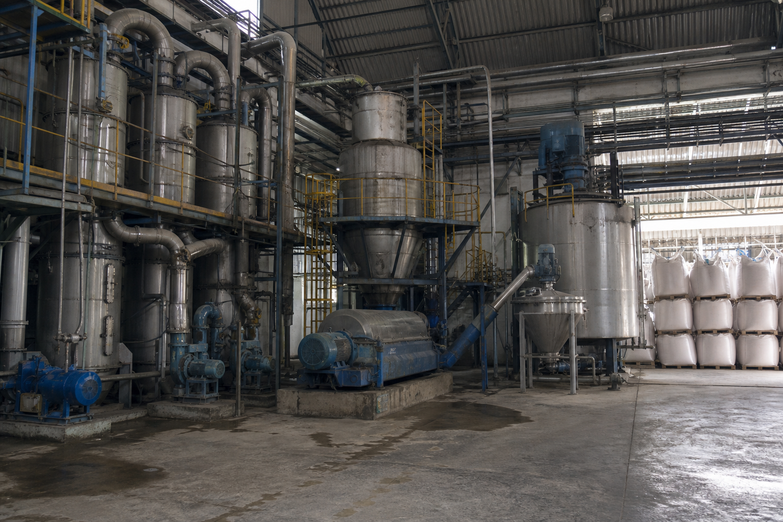
Salt separation plant: multi-effect evaporator train, crystallizer, centrifuge and bagged separated salt products
At a Glance

Salt Separation in Four Numbers

Reference figures from published salt-separation and resource-recovery system data on mixed-salt and potash streams.

Separated Salt Purity
NaCl ≥95% · KCl ≥85%
published K–Na separation evaporator duty; potash recovery streams reach >99% K₂SO₄ (FCO grade)
Feed Concentration Range
0.5–30%
dilute through near-saturated feeds go straight to evaporation; below ~0.5% membrane pre-concentration is the economic route
Evaporation Capacity
up to 50,000 L/h
published K/Na separation train: four-effect forced circulation + vacuum flash + cooling crystallization
Systems Suited
≤3 salts
selective sequential crystallization applies where the salts show distinct solubility behavior
System & Process Flow

Two Separation Routes, One Engineered Train

Evaporation concentrates the liquor; selective crystallization splits the salts; solids handling turns each fraction into a bagged product — with mother liquor looping back closed-circuit.

Simplified Salt Separation & Resource Recovery Diagram

Mixed-salt feed → Pretreatment (filtration / pH) → Evaporator train (MEE / MVR) → Salt crystallizer (NaCl) → Centrifuge → Dryer → Salt product · Mother liquor → Cooling / freeze crystallizer (Na₂SO₄) → Centrifuge → Sulfate product · Mother liquor return (purge to dryer)

The evaporation train takes out water and crystallizes the first salt; the cooled mother liquor crystallizes the second; a controlled purge keeps impurities from accumulating — every stream leaves as product, distillate or a small handleable residue.

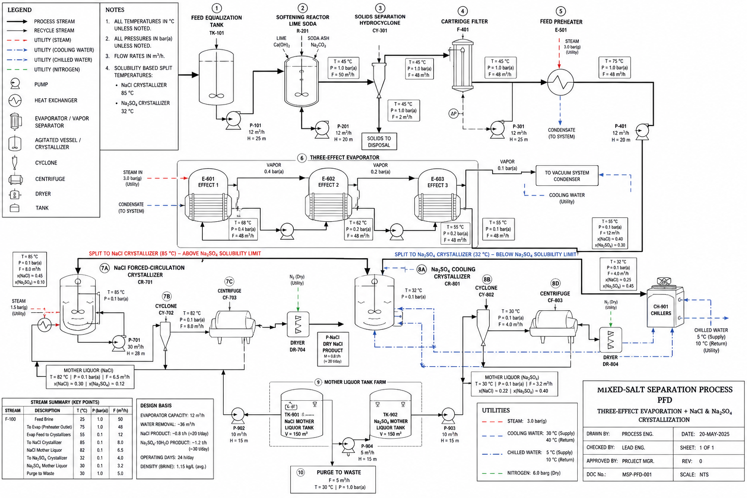
Mixed-salt separation PFD: three-effect concentration, NaCl forced-circulation crystallizer and Glauber salt cooling crystallizer with separate centrifuges and dryers
01
Pretreatment & Feed Routing
Feeds from 0.5–30% salinity run straight to evaporation; below ~0.5% a membrane stage pre-concentrates (single membrane ≤0.45 m³/h) before the thermal train.
02
Evaporative Concentration
MEE or MVR drive the concentration stage — MVR configurations report energy savings of 60%+ versus conventional evaporation on comparable salt duties.
03
Selective Crystallization
Ternary phase-diagram analysis with the lever rule fixes which salt leaves first and at what yield — evaporative crystallization for NaCl, cooling / freeze crystallization for the sulfate or low-temperature salt.
04
Solids & By-Product Recovery
Centrifuge, dry and bag each salt fraction; mother liquor returns closed-circuit; desalted residues go to building-material use — zero-waste resource recovery that offsets ZLD operating cost.
ROUTE A · NACL–NA₂SO₄
Salt–Glauber Separation (Salt–Nit Co-Production)
Evaporative crystallization recovers NaCl while the liquor is still hot; the mother liquor is then cooled — or frozen — to crystallize sodium sulfate (glauber salt). Both salts leave as separate bagged products; the depleted liquor recycles. On mixed Na₂SO₄/NaCl systems this route is the published basis for co-production and by-product-salt resource recovery.
Split order and yields from ternary phase diagram + lever rule; separated salts meet national by-product salt standards for direct resource use.
ROUTE B · NACL–KCL
Potash Recovery (K–Na Separation)
KCl solubility climbs steeply with temperature while NaCl stays nearly flat — so a four-effect forced-circulation train with vacuum flash crystallizes NaCl first at temperature, then cooling crystallization recovers KCl from the cold mother liquor. Closed-circuit mother liquor recirculation lifts overall recovery; MVR drive is an option on the same flowsheet.
Published duty: NaCl ≥95% / KCl ≥85% purity, TA2 titanium wetted parts, for systems of up to three salts with distinct solubility behavior.
Technical Specifications

Published Data Across the Separation Train

Aggregated from published supplier data on salt-separation, potash-recovery and mixed-salt resource systems — indicative figures for preliminary screening, not a process guarantee.

System SectionParameterRange / RatingCondition
Feed & pre-concentrationFeed concentration range0.5–30%dilute to near-saturated brines go directly to the evaporative train
Membrane pre-concentrationbelow ~0.5% · ≤0.45 m³/h per membraneeconomic route for very dilute feeds ahead of evaporation
Chemical consumptionnear-zero reagentevaporative crystallization adds almost no chemicals; no resin or exchange-membrane consumables
K–Na separation trainsEvaporation capacity50,000 L/hpublished four-effect forced-circulation + vacuum flash + cooling crystallization duty
Separated salt purityNaCl ≥95% · KCl ≥85%stepwise crystallization: NaCl crystallizes first hot, KCl later cold
Drive configurationMEE or MVRboth configurations available on the same process scheme
MaterialsTA2 titanium · SS304 / carbon steelwetted parts titanium; non-wetted structural parts SS304 or carbon steel
Mother liquor & suitabilityclosed-circuit return · ≤3 saltsfor systems with distinctly different solubility behavior
Mixed-salt (Na₂SO₄/NaCl) separationSeparation methodcooling crystallization + selective salt splitmulti-effect circulation + forced evaporation + controlled crystallization separation
Split design basisternary phase diagram + lever rulefixes crystallization order and per-salt yields before hardware is sized
Product grade & energyby-product salt standard · MVR −60%+separated salts resource-use grade; mother-liquor drying unit recovers the balance
Resource recoveryPotash product purity>99% K₂SO₄FCO grade white crystals from incineration-ash potash recovery
Recovery process chain6 stepsash conditioning (pH) → filtration → MEE concentration → evaporation crystallization → centrifuge purification
Residue valorizationzero-wastedesalted residue to brick / building-material use; recovery revenue offsets ZLD operating cost

Figures aggregate published supplier specifications and project data on salt-separation and resource-recovery systems (separation evaporator builders, wastewater evaporation contractors, potash-recovery technology providers). Purity and capacity values are duty-specific — your feed’s salt composition and phase behavior govern what is achievable; send a full water analysis for a case-specific assessment.

Reference Configurations

Three Duties, Three Trains

The same separation logic — concentrate, crystallize selectively, close the liquor loop — dressed three ways by feed and product target.

CONFIG A · MIXED-SALT RESOURCE RECOVERY
ZLD Mixed Salt to By-Product Salt
Evaporator train with controlled crystallization separation on high-salinity wastewater: multi-effect circulation concentrates the liquor, selective crystallization splits the salts, and a mother-liquor drying unit recovers the balance. Separated salts reach by-product salt standard for direct resource use — salt becomes revenue, not landfill.
by-product gradeseparated salts resource-use standard; MVR option −60%+ energy
CONFIG B · SALT–GLAUBER CO-PRODUCTION
NaCl–Na₂SO₄ Salt–Nit Co-Production
Two crystallization stages in series: evaporative crystallization for NaCl while hot, cooling / freeze crystallization for sodium sulfate from the mother liquor. Two bagged products from one feed, with the depleted liquor recycling closed-circuit and a controlled purge keeping impurities bounded. The reference route on mixed Na₂SO₄/NaCl brines.
2 products · 1 trainsplit order set by ternary diagram + lever rule
CONFIG C · HIGH-PURITY SALT & POTASH
K–Na Separation & Salt Refining
Four-effect forced circulation with vacuum flash and cooling crystallization, MEE or MVR driven, in TA2 titanium wetted parts. Stepwise crystallization separates NaCl at temperature and KCl cold; closed-circuit mother liquor lifts recovery. The duty class behind ≥95% NaCl / ≥85% KCl splits and >99% potash products.
NaCl ≥95% · KCl ≥85%potash streams to >99% K₂SO₄ FCO grade
Reference Installations

What These Systems Achieve on Site

Anonymized configurations reconstructed from published supplier project data.

AMMONIUM SULFATE SALT SEPARATION
Three-Effect Evaporation + Salt Split
Ammonium sulfate wastewater concentrated in a three-effect evaporator, then split by multi-effect circulation, forced evaporation and controlled crystallization separation. Mixed Na₂SO₄/NaCl systems on the same flowsheet run cooling crystallization for selective separation; separated salts reach by-product salt standard, with a mother-liquor drying unit recovering the balance.
MVR −60%+energy vs. conventional evaporation on comparable duty
POTASH FROM INCINERATION ASH
Ash-to-Potash Resource Recovery
Patented potash recovery from incineration-boiler fly ash: ash conditioning with pH adjustment, filtration and separation, MEE concentration, evaporation crystallization and centrifuge purification deliver >99% K₂SO₄ FCO-grade white crystals. The desalted residue goes to brick making — zero-waste, retrofit-friendly, and the first commercial unit is operating.
>99% K₂SO₄FCO grade · desalted residue to building material
BATTERY-RECYCLING BRINE SPLIT
Salt Recovery from Hydromet Tailwater
Lithium-ion battery hydrometallurgical recycling wastewater from 0.5–30% salinity: dilute feeds pre-concentrate on membranes (≤0.45 m³/h per unit) before evaporation crystallization, which runs with near-zero reagent and no resin or exchange-membrane consumables. Sodium sulfate and nickel–cobalt–manganese sulfates leave as separated recoverable salts.
0.5–30% feednear-zero reagent · no consumable exchange parts
Positioning & Evidence

This page aggregates published supplier specifications and project data (separation-evaporator builders, wastewater evaporation contractors, potash-recovery technology providers) into an engineering screening view. All names are withheld; configurations are described generically. Purity and capacity figures are duty-specific published values, not universal guarantees — separation performance is governed by your feed’s salt composition and phase behavior, and must be confirmed against a full water analysis.

FAQ · Engineering Answers

Salt Separation Questions We Answer Most

Recurring questions from engineers assessing mixed-salt resource recovery.

QCan my mixed-salt stream actually be separated?

Sequential selective crystallization suits systems of up to about three salts whose solubility behavior is distinctly different — NaCl–Na₂SO₄ and NaCl–KCl are the two classic pairs. The first screening step is a full salt-composition analysis laid on the phase diagram: if the salts’ solubility curves diverge across the operating temperature range, a separation route exists.

QHow is the crystallization order decided in salt–glauber separation?

By ternary phase-diagram analysis with the lever rule — the published design basis for mixed Na₂SO₄/NaCl systems. The diagram fixes which salt crystallizes first as water is removed, at what concentration the second salt drops out, and the recoverable yield of each fraction; hardware is sized only after that split is calculated.

QMy feed is dilute — does separation still make sense?

Evaporative separation handles feeds from roughly 0.5% to 30% salinity. Below ~0.5%, a membrane pre-concentration stage (single membranes rated up to 0.45 m³/h) lifts the salinity to where thermal separation is economic. The comparison against the alternatives matters too: evaporation crystallization consumes almost no chemicals and carries no resin or exchange-membrane consumables.

QWhat purity can the separated salts reach — and can they be sold?

Published K–Na separation duty reports NaCl at ≥95% and KCl at ≥85%; mixed-salt separation reports separated salts at national by-product salt standard — the grade that allows direct resource use rather than disposal. On potash recovery duties, >99% K₂SO₄ (FCO grade) white crystals are in commercial operation. Marketability still depends on your local by-product regulations.

QMEE or MVR — which drive for a separation train?

Both run on the same flowsheet — published systems offer either configuration. MVR variants report energy savings above 60% versus conventional evaporation on comparable salt duty, at the cost of compressor capital and a power supply; MEE trades energy for simplicity where live steam is cheap. The choice is an energy-price calculation, not a process constraint.

QWhat happens to the residues and the mother liquor?

Mother liquor returns closed-circuit to the evaporator train, with a controlled purge keeping impurities bounded — a mother-liquor drying unit can recover the balance as solid. Desalted residues need not be landfilled: in the published potash-from-ash system, the depleted residue goes to brick making, making the recovery loop zero-waste and offsetting ZLD operating cost.

Salt Separation in the Field — Case Studies & Technical Guides

Sitting on a Mixed-Salt Stream?

Send the full water analysis — salt composition, concentration range, daily volume and any purity targets. We will return a phase-diagram separation assessment with the crystallization route and an indicative equipment configuration — not a brochure.

Request a Proposal

Send your feed characterization (TDS, COD, main salts, viscosity), throughput and product targets — we respond with a preliminary process route within two business days.