
EvapCryst logo

Forced-Circulation Evaporation Systems

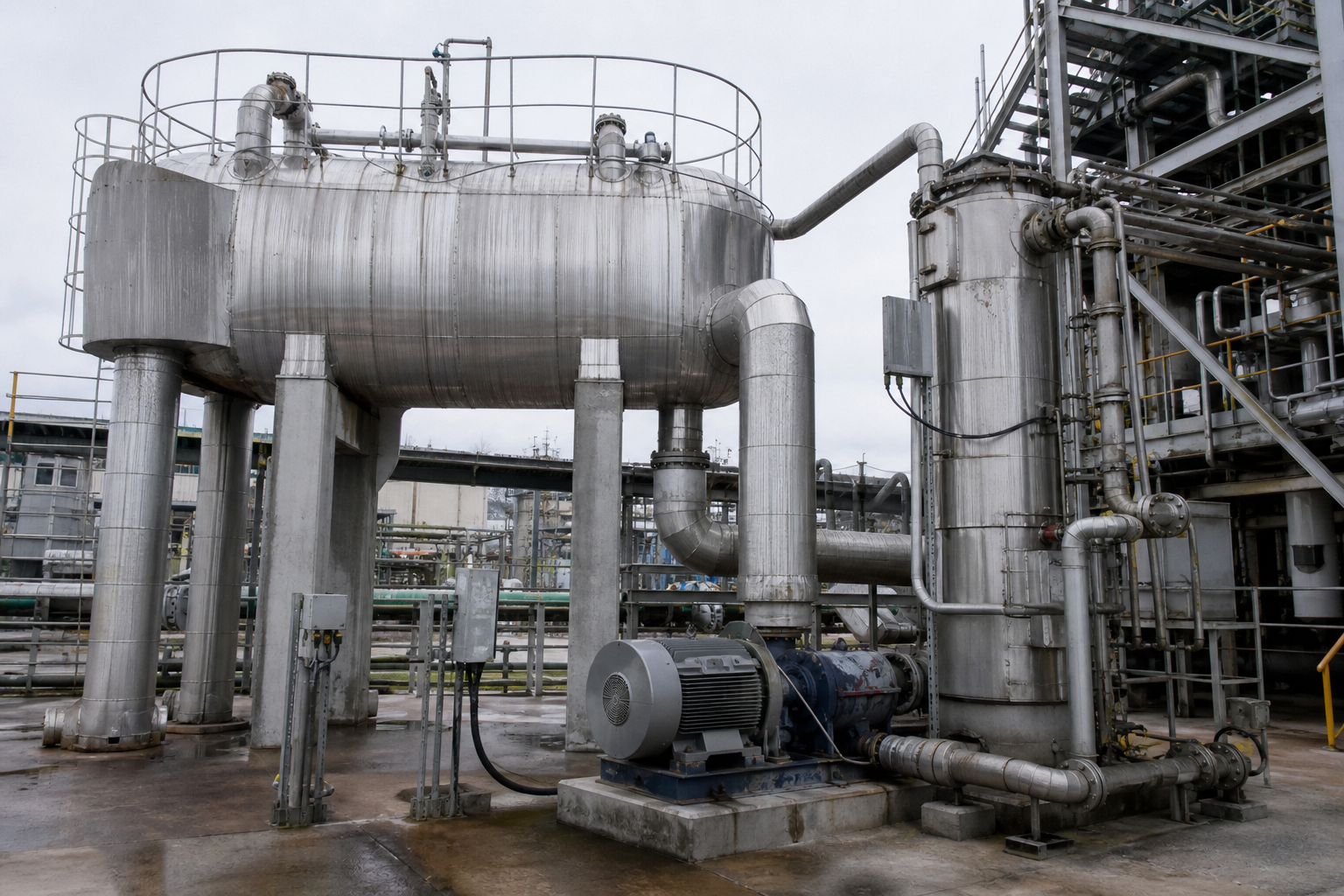
An external circulation pump pushes liquor through the heat exchanger at high velocity, suppressing boundary-layer boiling and scale deposition. Higher pumping energy than falling film — but the standard choice for high-TDS, scaling-prone, high-viscosity and crystallizing feeds where a falling-film distributor would foul within hours.

Forced circulation evaporator with external circulation pump and heat exchanger
At a Glance

Four Numbers That Define Forced-Circulation

Reference ranges under typical operating conditions — where your project lands inside each range depends on feed TDS, scaling tendency and viscosity.

Circulation Velocity
2–3 m/s
tube-side velocity — keeps crystals suspended and suppresses wall nucleation and scale deposition
Heater Temperature Rise
≤10 °C
temperature rise across the heater held low to prevent boiling on the tube wall and tube-wall incrustation
Feed Scope
High-TDS · scaling · crystallizing
the feeds where falling film fouls within hours — ZLD brines, coal-chemical wastewater, high-viscosity liquors
Circulation Pump Power
Project-specific
per-m² pumping duty is set per installation — qualitatively higher than falling-film service
Working Principle

One Loop, Two Operations

In forced-circulation service, evaporation and crystallization usually happen in the same circulating loop rather than in sequence — the liquor is heated below its boiling point and flashes in the separator, and crystals grow in the circulating slurry.

Simplified Forced-Circulation Flow Diagram

Feed → Circulation pump → Heater (below boiling, ΔT ≤10 °C) → Flash in separator → Vapor out + slurry circulated

Supersaturation generated by the flash is relieved on suspended crystals in the same loop — which is why forced-circulation evaporation and forced-circulation crystallization share one architecture.

01

Circulation

The external pump drives liquor through the heater at 2–3 m/s tube-side — high enough velocity to keep crystals suspended and stop scale from settling on the wall.

02

Sensible Heating

The heater raises the liquor temperature without boiling it — the temperature rise is held at ≤10 °C so the tube wall never becomes a nucleation surface.

03

Flash Evaporation

Superheated liquor enters the vapor body at lower pressure and flashes: water evaporates, the liquor crosses saturation, and supersaturation appears in the bulk.

04

Crystal Growth in Loop

The supersaturation is relieved on suspended crystals circulating with the liquor; the slurry returns to the pump and the loop closes.

Selection

Where Forced-Circulation Wins

Fouling resistance outweighs energy cost — the configuration for difficult liquors, and for the high-concentration back end of cascade trains.

01 · DIFFICULT LIQUORS

High-Salinity ZLD Brines

High-TDS, scaling-prone and mixed-salt streams — the workhorse body for ZLD evaporator-crystallizer trains and coal-chemical wastewater concentration.

Fouling resistancecontinuous stable operation on feeds where classified-bed configurations would foul or cement
02 · CASCADE BACK END

Final Concentrator Duty

In cascade trains — e.g. Kraft black liquor or any feed that starts clean and finishes dirty — falling film takes the low/medium-solids stages and forced-circulation finishes at high solids where viscosity, scaling and boiling-point elevation peak.

Cascade patternfalling film front + forced-circulation crystallizing end — a documented hybrid configuration
03 · CRYSTALLIZING SERVICE

Evaporator-Crystallizer Bodies

When concentration must end in salt production, the forced-circulation body becomes the crystallizer itself — see the FC crystallizer page for the crystal-side design logic.

One architectureevaporation and crystallization in the same circulating loop, not in sequence
Technical Specifications

Forced-Circulation System Envelope — Published Supplier Data

Indicative ranges aggregated from published supplier specifications of forced-circulation evaporator builders (steam-driven and MVR-driven, salt and wastewater executions). For route screening only — not a process guarantee for any specific project.

System SectionParameterPublished Indicative RangeApplies To / Basis
Circulation loopTube velocity1–5 m/s published window · 2–3 m/s typical screeningthe anti-fouling mechanism itself — high shear keeps the heat surface clean
Whole trainCapacity range1–30 t/h published range · 1.5 t/h vacuum-salt units · CFE class 500–4,000 gph (≈1.9–15 m³/h)single salt trains to packaged wastewater units
Whole trainSpecific energy15–40 kWh per t on MVR drive · 30–60 kWh/t configuration classthe highest of the film family — the price of circulation pumping
Whole trainShell-side pressure6–25 kPa(abs) · single-effect published 8–25 kPa(abs)vacuum flash operation
EnergySteam economy (steam-driven)single effect ≈1.0 · +TVR / heat recovery → 1.5–2.2steam-driven variants; MVR drive takes the electric route
ElectricalPower supply440/480 V 60 Hz · 380–480 V LV · 3.3–11 kV MVVFD soft-start, anti-surge, optional AFE harmonic filter
Whole trainTurndown50–100%circulation and compressor control
SeparationDemisting stages4-stage: vane inlet → vessel-diameter dropout → chevron → mesh padcrystal-carryover control on salt duties
Heat exchangerExecutionshell-and-tube, straight or U-tube, removable bundle · plate route alternativemechanical cleaning access vs compactness
PumpsCirculation pump classslurry-class, dual mechanical seals, open impeller, seal flushcontinuous duty on crystal slurries
MaterialsWetted partsSS316L · duplex · Ti · Hastelloychloride chemistry selection
Vessel codeExecution standardASME VIII design with rupture-disc over-pressure reliefpublished packaged CFE executions with automated start-to-CIP

Ranges aggregate published specifications from forced-circulation evaporator builders (salt, wastewater and brine executions). Figures are supplier-published indicative values for screening; a project number requires heat and mass balance on your feed, solids content and scaling-chemistry data.

Main Process Modules

The Train, Module by Module

Each module is selected on feed chemistry and duty — the envelope column gives published operating ranges per module type, not a single-project specification.

ModuleEquipment TypesSelection BasisIndicative Operating Envelope
Circulation loopShell-and-tube calandria + circulation pumphigh tube velocity suppresses fouling and crystal blockage1–5 m/s tube velocity; boiling happens in the flash separator, not on the heating surface
Flash separatorTangential-entry vesselpressure let-down flashes the superheated liquor off the heat surfaceshell 6–25 kPa(abs)
Demister trainVane inlet · chevron · mesh pad (4 stages)droplet and crystal carryover controlmesh-pad alloy follows the vessel
Heat exchangerStraight / U-tube removable bundle · plate alternativemechanical-cleaning access vs compactnesscrystallizing and fouling duties take the removable bundle
Circulation pumpSlurry class, dual mechanical sealcontinuous duty on crystal slurriesopen impeller, seal flush, solids tolerance
Vapor sideMVR compressor · next-effect steam · TVRenergy strategy per site utilities15–40 kWh/t MVR class · SE 1.0 → 1.5–2.2 with TVR
Salt handlingDownstream crystallizer / separator / salt removalcrystallizing duties close the loop into solidsNaCl · Na₂SO₄ · NH₄Cl · CoSO₄ · NiSO₄ · LiOH — 20+ salts in published coverage

Module envelopes follow the published supplier data above; circulation rate, ΔT split and flash pressure are project-specific and set at design.

Forced-Circulation in the Field — Case Studies & Technical Guides

External circulation evaporator station with external calandria and vapor heads
Technology

External and Natural Circulation Evaporators

External circulation evaporators run the loop outside the boiling vessel; natural circulation drives it by thermosiphon alone. Design numbers that decide fouling or clean operation: 4-6 m liquid head, circulation

Read More »
Industrial evaporation plant process hall with falling film evaporator bodies and forced circulation crystallizer
Technology

Process Flow Design for Evaporation Plants

How the process flow sheet of an evaporation plant is decided: feed and site inputs, material and energy balances, falling-film + forced-circulation combinations, MVR design principles, materials selection, and PFD-to-3D

Read More »
One Decision of Four — Not a Standalone Choice

Forced-circulation is a Dimension B process configuration. It combines freely with any Dimension A energy strategy — MVR-driven forced-circulation is a standard ZLD pattern (MVR + Forced-Circulation + Evaporative + FC) — and with any Dimension C/D crystallization decision. The energy penalty versus falling film is pumping power; whether that penalty is acceptable is decided by the fouling assessment, not by catalog preference. All figures on this page are indicative ranges for preliminary screening, not a process guarantee.

FAQ · Engineering Answers

Forced-Circulation Questions We Answer Most

Recurring questions from engineers weighing forced-circulation against falling film.

QWhy not just use falling film with a better distributor?

Because on scaling-prone, high-TDS or crystal-bearing feeds the problem is not distribution quality — it is that the feed deposits scale and crystals on any surface where boiling occurs. Forced-circulation removes boiling from the tube wall entirely (heater ΔT ≤10 °C, no wall boiling) and holds 2–3 m/s velocity so nothing settles. Falling film would foul within hours on the same feed.

QIs forced-circulation evaporation the same equipment as an FC crystallizer?

The architecture is the same — external pump, heater, flash separator, loop. The difference is objective and design emphasis: this page covers stable concentration of difficult liquors; the FC crystallizer page covers crystal growth, slurry control and discharge. In ZLD service one vessel usually does both.

QWhat does the high velocity cost me?

Pumping power — forced-circulation carries a standing circulation-pump duty that falling film does not. The specific per-m² pumping energy is project-specific; qualitatively, operators accept it in exchange for continuous stable running on feeds where anything else stops.

QWhen is forced-circulation the better retrofit choice?

When scaling, fouling and high TDS dominate the existing plant's problems. When the feed is clean, low-viscosity and heat-sensitive, falling film is the better retrofit. See the retrofit feasibility discussion on Energy Retrofit & Decarbonization.

Screening Forced-Circulation for Your Feed?

Send us feed analysis (TDS, scaling tendency, viscosity, crystal content) and throughput. We will return a preliminary falling-film vs. forced-circulation screening with an indicative configuration — not a brochure.

Request a Proposal

Send your feed characterization (TDS, COD, main salts, viscosity), throughput and product targets — we respond with a preliminary process route within two business days.