
EvapCryst logo

Forced-Circulation (FC) Crystallizer

Engineering reliability first. An external loop circulates a crystal slurry at 2–3 m/s through the heater and back, relieving moderate flash-generated supersaturation on suspended crystals. Medium crystals, wide distribution — and continuous stable operation on the high-TDS, scaling, mixed-salt systems where anything else stops.

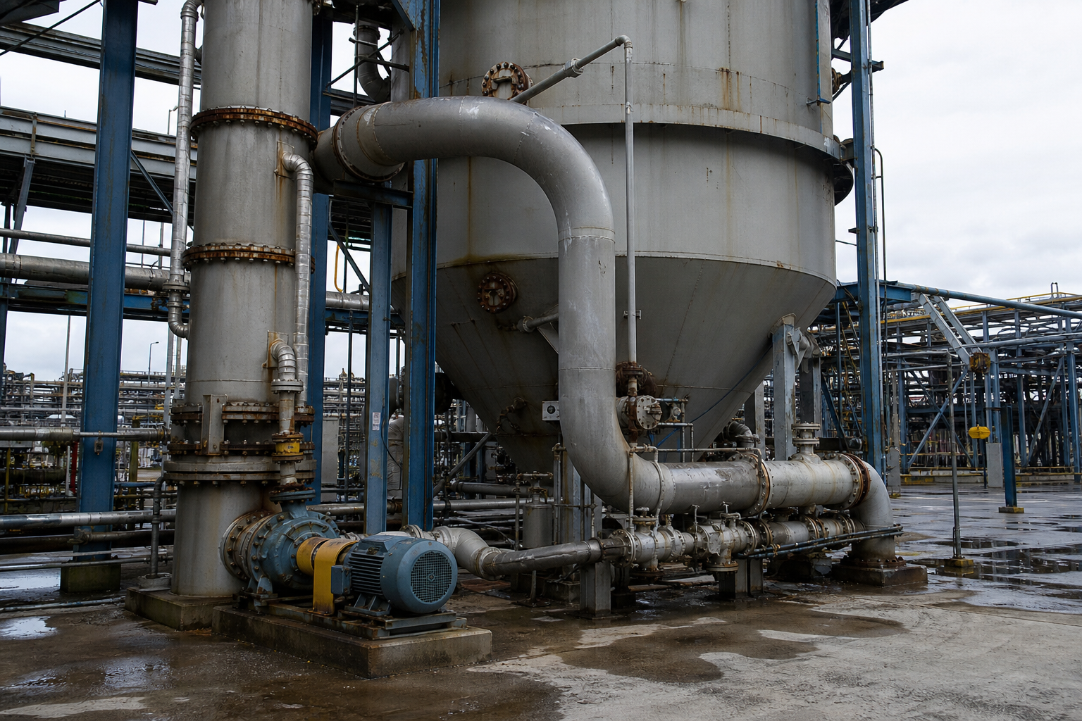
Forced circulation FC crystallizer with external circulation loop
At a Glance

Four Numbers That Define FC

Reference ranges under typical operating conditions on inorganic salt systems.

Crystal Size (d50)
0.2–0.8 mm
moderate size, wide distribution — no internal classification; actual PSD depends on residence time and fines management
Circulation Velocity
2–3 m/s
tube-side velocity keeps crystals suspended, suppresses wall nucleation and stops scale settling
Supersaturation Level
Moderate
generated by flash in the loop and controlled by circulation rate and heater ΔT (≤10 °C)
Slurry Density Range
Operator-set
slurry density is controllable across FC operation — operating bands are set per application and duty
Working Principle

Circulate, Flash, Grow, Repeat

The same circulating architecture as forced-circulation evaporation — with crystal slurry control added as the design objective.

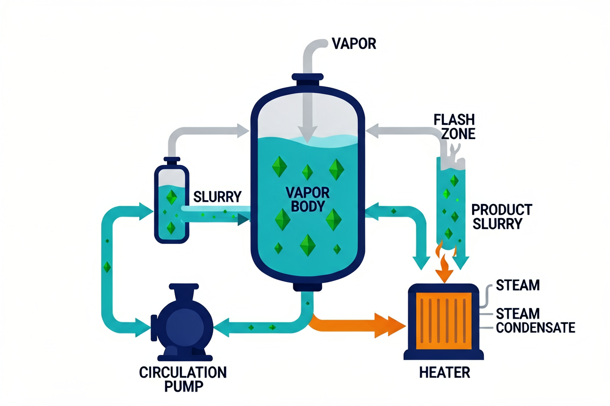
Simplified FC Crystallizer Flow Diagram

Slurry → Circulation pump → Heater (ΔT ≤10 °C, no wall boiling) → Flash in vapor body → Supersaturation relieved on suspended crystals → Loop

Supersaturation never touches a hot wall — it is created by the flash in the vapor body and consumed by the suspended crystals in the loop.

01

Slurry Circulation

The external pump keeps a crystal slurry moving at 2–3 m/s — nothing settles, nothing scales undisturbed.

02

Sensible Heating

The heater warms the slurry without boiling it — the ≤10 °C rise keeps the tube wall out of the nucleation business.

03

Flash & Supersaturation

In the vapor body the slurry flashes; concentration crosses saturation and moderate supersaturation appears.

04

Growth & Discharge

Crystals in the loop consume the supersaturation; product slurry is drawn off continuously to separation.

Configuration Selection

FC vs. DTB vs. Oslo

Three vessel configurations, three priorities: FC puts engineering reliability first, DTB puts product quality first, Oslo puts crystal quality first.

ParameterFC (this page)DTBOslo
Selection priorityEngineering reliabilityProduct quality (narrow PSD)Crystal quality (large, pure)
Typical crystal size0.2–0.8 mm — moderate, wide distribution0.5–2.0 mm — larger, controlled1.0–5.0 mm — large, very uniform
Fines removalNone standard — no internal classificationYes — classified-fines removal loop (elutriation zone)Natural — classification by fluidization
Circulation velocity2–3 m/s external loop1–2 m/s internal draft tube0.02–0.05 m/s fluidization upward velocity
Supersaturation toleranceHigh — recirculation dilutesMedium — controlled by draft-tube velocityLow — ≤1–2 g/L to avoid spontaneous nucleation
Best forHigh-salinity, scaling-prone, mixed-salt systems: NaCl, Na₂SO₄, ZLD mixed saltsFertilizer (NH₄)₂SO₄, KCl, battery-grade Li₂CO₃ precursor, organic acidsBattery-grade NiSO₄ / CoSO₄ / MnSO₄, pharma intermediates, electronic-grade salts

d50 ranges reflect typical operating distributions on inorganic salt systems; actual PSD depends on residence time, fines management, seed control and the cooling/evaporation profile.

Selection

When to Pick FC — and When Not To

FC is the answer when fouling resistance and on-stream time outweigh crystal size; the wrong answer when product spec needs classification.

Forced circulation crystallizer system with flash body, external heat exchanger and circulation pump
Technology

FC Crystallizer: Principle and Application

An FC (forced-circulation) crystallizer is the industrial workhorse for high-viscosity, fouling-prone and impurity-laden liquors. This guide explains its structure, working cycle, key design parameters, MVR integration and how it compares

Read More »
Technical Specifications

FC Crystallizer System Envelope — Published Supplier Data

Indicative ranges aggregated from published supplier specifications of forced-circulation crystallizer builders (salt, ZLD brine and chemical executions). For route screening only — not a process guarantee for any specific project.

System SectionParameterPublished Indicative RangeApplies To / Basis
Product crystalPSD window0.2–0.8 mm mixed-suspension band · salt cuts 0.2–0.5 / 0.5–1.2 / 1.2–2.5 mm with seed managementno internal classification — the wide distribution is the documented trade
Circulation loopSlurry velocity2–3 m/s typical · 1–5 m/s published windowkeeps crystals suspended and stops scale settling on the heat surface
Supersaturation controlGeneration & steeringflash at the body · heater ΔT ≤10 °C · seed system + slurry-density controlheld moderate, inside the metastable zone
Body architectureFC circuit compositioncrystallizer body (conical salt discharge) + circulation pipe + axial-flow pump + heat exchangerpublished FC composition: slurry reheated in the exchanger, flashed in the body, looped back
Whole trainCapacity range0.5–2 t/h double-effect · 3–50 t/h triple-effect · 30 t/h MVR crystallization references · salt plants 5–500 t/dZLD brine service to merchant salt
Whole trainSpecific energyMVR drive 15–40 kWh per t water (15–50 published window) · DE SE 1.8–2.2 · TE SE 3.5–4.0 kg/kgenergy form follows site utilities
Thermal profileEffect temperatures3-effect salt 99/76/53 °C · double-effect 80–90 / 55–70 °C · low-temp ladder ~80→40 °Cpublished multi-effect profiles feeding the FC body
Product qualityPurity & moistureNaCl ≥99.2% (to 99.9%) · final free moisture ≤0.2%purification skid + centrifuge + fluidized-bed drying
On-streamCIP interval≥10–20 dayscirculation velocity is itself the anti-fouling mechanism
MaterialsWetted partsSS304/316L · duplex · Ti optionalchloride and scaling chemistry selection

Ranges aggregate published specifications from forced-circulation crystallizer builders (salt, wastewater and ZLD brine executions). Figures are supplier-published indicative values for screening; a project number requires heat and mass balance on your feed, scaling chemistry and PSD target.

Main Process Modules

The Train, Module by Module

Each module is selected on feed chemistry and duty — the envelope column gives published operating ranges per module type, not a single-project specification.

ModuleEquipment TypesSelection BasisIndicative Operating Envelope
Feed conditioningBrine purification skid — dissolve / soften / clarify / polishliquor quality sets the product ceilingpublished NaCl lines purify ahead of the effects
Pre-concentrationMulti-effect or MVR evaporatorapproach saturation without premature nucleation3–50 t/h · 99/76/53 °C three-effect profile
Supersaturation generationExternal heater + flash at the FC bodykeep boiling off the heat surfaceheater ΔT ≤10 °C · liquor superheated, then flashed
FC growth bodyBody + axial-flow pump + exchanger loopslurry-class recirculation with conical salt discharge2–3 m/s loop velocity · slurry recirculates through the heater
Fines & seed managementSeed addition + slurry-density control · fines dissolutionPSD steering without classification internalsseeded executions publish all three salt cuts, 0.2–2.5 mm
Solid–liquid separationThickener → peeler / pusher centrifugedewater the wide-PSD slurrypusher class 1100 mm basket on coarse cuts
Drying & screeningFluidized-bed / vibration dryer + sievemoisture and cut controlfinal free moisture ≤0.2%
Mother liquorClosed loop to the final effect · purge streamimpurity bleed vs yieldpublished Na₂SO₄ / NaCl trains run mother liquor closed-loop

Module envelopes follow the published supplier data above; circulation rate, heater ΔT and seed rate are project-specific and set at design.

FC Crystallizer in the Field — Case Studies & Technical Guides

Forced circulation crystallizer system with flash body, external heat exchanger and circulation pump
Technology

FC Crystallizer: Principle and Application

An FC (forced-circulation) crystallizer is the industrial workhorse for high-viscosity, fouling-prone and impurity-laden liquors. This guide explains its structure, working cycle, key design parameters, MVR integration and how it compares

Read More »
Positioning & Evidence

FC is a Dimension D crystal growth configuration — it pairs with any Dimension C supersaturation method, and it is the typical carrier for evaporative crystallization on difficult liquors. The selection logic is explicit: accept higher energy consumption in exchange for continuous stable operation on high-salinity, high-viscosity, scaling-prone systems. What you give up is crystal size control — no internal classification means wide PSD. All figures are indicative ranges for preliminary screening, not a process guarantee.

FAQ · Engineering Answers

FC Crystallizer Questions We Answer Most

Recurring questions from engineers choosing a growth configuration.

QCan I get a narrow PSD out of an FC crystallizer?

No — that is the trade. FC has no internal classification; crystal size lands at 0.2–0.8 mm with a wide distribution. If the product spec (or downstream centrifuge yield) needs narrow PSD, the answer is DTB with classified-fines removal, not a tuned FC.

QWhat happens if I pick the wrong configuration?

You feel it in three places: product spec — undersized d50 fails downstream handling; availability — putting Oslo on a fouling-prone feed drives cleaning cycles that kill on-stream time; yield — fines escaping the crystallizer carry dissolved product back and increase purge.

QWhy does evaporative crystallization pair with FC?

Because once evaporation is the supersaturation driver, supersaturation is high and scaling accompanies it. The FC body at 2–3 m/s tolerates what a classified bed would not — that is exactly the ZLD mixed-salt duty.

QIs an FC crystallizer the same equipment as forced-circulation evaporation?

The architecture is identical — pump, heater, flash body, loop. This page covers crystal-side design: slurry control, residence and discharge. The evaporation-side logic (stable concentration of difficult liquors) lives on the FC evaporation page.

Screening an FC Configuration?

Send us feed composition, fouling tendency, target PSD and purity. We will return a preliminary FC vs. DTB vs. Oslo screening with indicative crystal size — not a brochure.

Request a Proposal

Send your feed characterization (TDS, COD, main salts, viscosity), throughput and product targets — we respond with a preliminary process route within two business days.