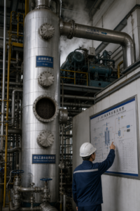
Produced water from oil and gas operations is desalinated by MVR evaporation at well sites, gathering stations, and refineries because the alternatives — deep-well injection under tightening regulation and long-haul trucking — keep rising in cost while water itself becomes the asset. The engineering problem reduces to three variables: oil and solids removal ahead of the evaporator, chloride-driven metallurgy, and turndown wide enough to absorb well-flow swings. Externally published reference projects — not EvapCryst project records — put the results in concrete terms: a Southeast Asian refinery treating more than 1,500 m³ per day of oily wastewater cut energy use by nearly 80% versus its previous steam-driven evaporator and halved freshwater demand, while onshore installations in water-scarce regions recover up to 90–95% of produced water for reuse: vendor-reported, indicative figures, not project guarantees.
What Is in Produced Water, and Why It Varies So Much
Produced water is formation water carried up with hydrocarbons; its composition tracks the geology more than the operator. Controlling parameters across oilfield, coalbed methane (CBM), and gas-field service — an illustrative envelope:
- TDS from 20,000 to 150,000 mg/L in hydraulic fracturing flowback, with extreme basins reaching 250,000–300,000 mg/L; produced water from conventional and CBM wells typically runs lower but rises over field life.
- COD of 100–5,000 mg/L, some basins higher, carried by hydrocarbons, additives, and flowback chemistries; the evaporator inlet should see less than roughly 500 mg/L.
- Suspended solids and oil, which must be reduced to about 10 mg/L SS and free-oil-free before the heat exchanger, or fouling dominates the maintenance budget.
- Hardness and silica — calcium, magnesium, and soluble silicon that form hard scale on heating surfaces if not softened out.
Coalbed methane water is its own case: comparatively moderate salinity but high hardness and silica with colloidal fines, and volumes that grow as the field matures. The design consequence for every variant is the same — full water analysis first, equipment selection second.
The Process Chain: Pretreat, Evaporate, Crystallize
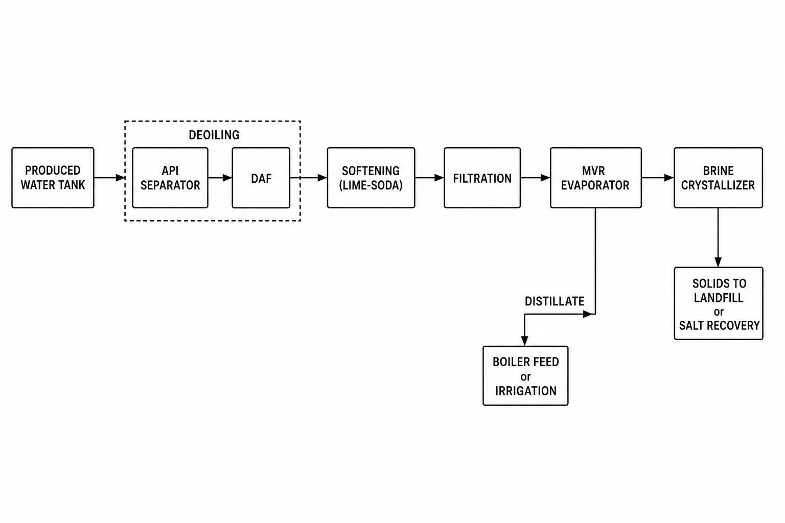
The working flowsheet is a three-block train. Block one, pretreatment: skimmers, API separators, and hydrocyclones strip free oil, sand, and coarse solids; coagulation-sedimentation, media filtration, and softening remove colloids and hardness so the feed meets its gates. Block two, MVR evaporation: boiling proceeds under vacuum at reduced temperature, and secondary vapor is compressed and returned as the heating medium — external steam serves only startup and shaft seals. Block three, crystallization and separation: concentrated brine flashes in the crystallizer, part recycles to hold TDS in band, and a centrifuge splits crystal salt from mother liquor, with distillate returning as reuse water.
| Process module | Equipment candidates | Selection basis | Indicative envelope |
|---|---|---|---|
| Pretreatment | Skimmers, API separators, hydrocyclones; coag-sed, media filtration, softening | Oil and hardness gates protect the evaporator | To COD <500 mg/L, SS <10 mg/L |
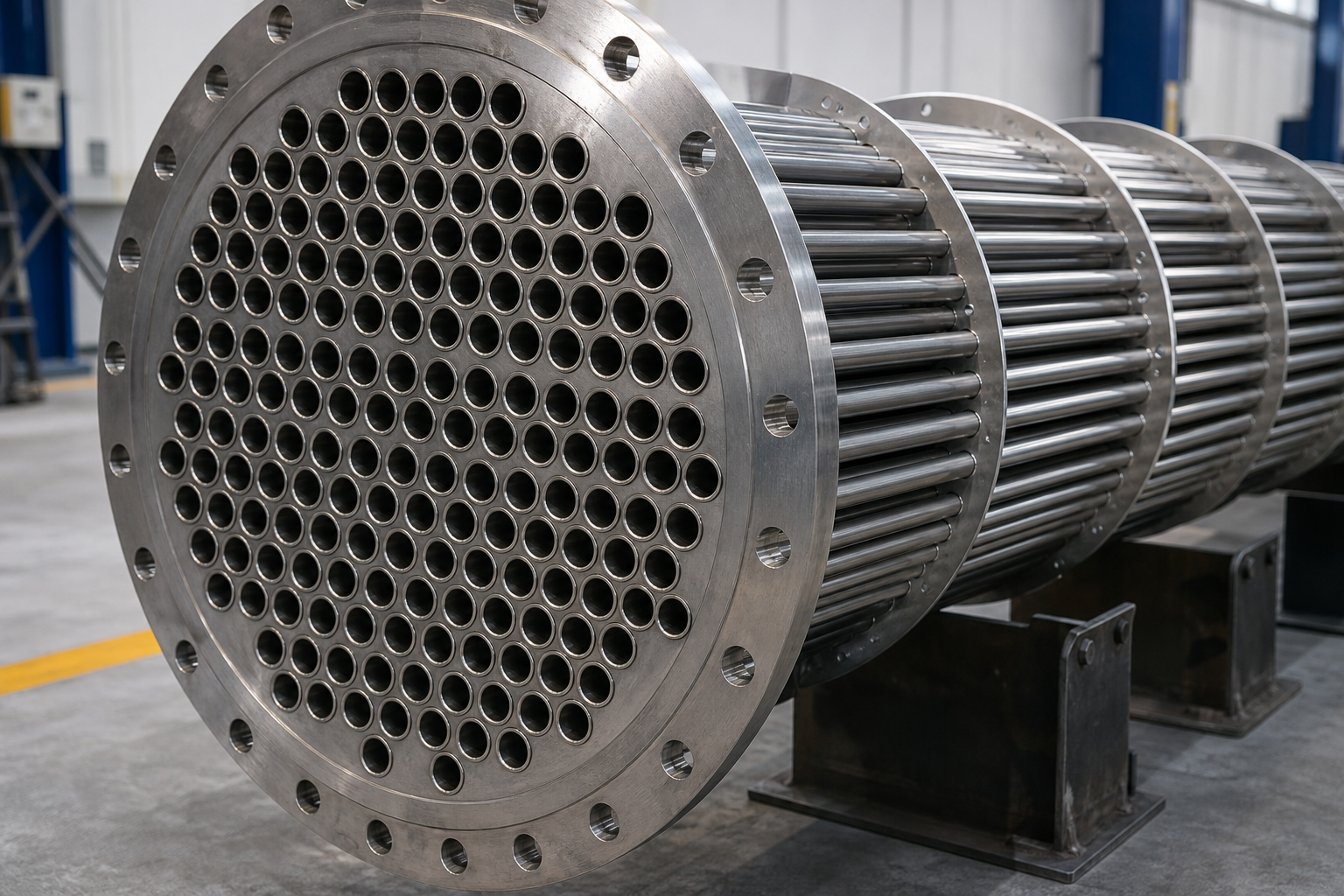
| MVR evaporation | Vacuum forced-circulation MVR unit | Chloride duty; low temperature slows scaling | 15–30 kWh/t; 1,500–3,000 W/(m²·K) |
| Vapor protection | Demister or secondary separator ahead of compressor | Rotor fouling is the top downtime cause | Per carryover load |
| Crystallization & separation | FC crystallizer with brine recycle + centrifuge | Stable saturation; salt from mother liquor | Controlled-interval purge |
Configuration, materials, and operating ranges depend on the actual water, corrosion review, scaling behavior, utilities, and project capacity.
One operating rule protects the machine that matters most: keep saline droplets out of the compressor. A demister or secondary separator ahead of the vapor line is standard, because rotor fouling from carryover is the leading cause of unplanned downtime on oily service. Condensate quality is tracked by conductivity and organics monitoring, and the brine side is purged at controlled intervals, so the crystallizer sees stable saturation.
Design Parameters That Decide Field Performance
The numbers below are the working selection envelope for MVR evaporators on produced water and flowback duty, consolidated from operating practice and the T/CIET 1598-2025 mechanical vapor recompression evaporator standard.
| Parameter | Working range | Design note |
|---|---|---|
| Evaporation temperature | 80 ± 2 °C (flowback); 50–70 °C under vacuum for CBM | Lower temperature slows scaling and organic decomposition |
| Operating pressure | 0.02–0.05 MPa absolute | Vacuum system sized for site altitude |
| Forced-circulation tube velocity | 1.5–3.0 m/s | Scours walls; mandatory once crystallizing |
| Heat transfer coefficient | 1,500–3,000 W/(m²·K) | Basis for heat-transfer area sizing |
| Compressor adiabatic efficiency | ≥ 80%, pressure ratio 1.2–2.0 | Temperature rise 8–20 °C; BPE of 8–12 °C needs 3–5 °C margin |
| Specific energy | 15–30 kWh per ton of water evaporated | The OPEX number for field economics |
| pH control band | 8–10 | Below 8 risks acid corrosion; above 10 drives CaCO₃/silicate scale |
| Feed gates | COD <500 mg/L, SS <10 mg/L | Non-condensable gas venting continuous and instrumented |
Metallurgy Follows the Chloride Ion
Chloride sets the wetted-materials budget more than any other variable, and the tiers are unambiguous. Below about 1,000 mg/L, 316L holds up; 1,000–5,000 mg/L takes 2205 duplex; above 5,000 mg/L — most flowback and much produced water, especially weakly acidic — titanium (TA2) tubes and wetted separator parts are the reliable option, with Hastelloy for the most aggressive chemistry. Non-wetted structure can remain coated carbon steel; the corrosion dollars concentrate on heat-exchange surfaces. Turndown is the second structural decision: flowback swings with well cleanup, so a 10–20% capacity margin plus variable-frequency drives track the swings without efficiency collapse.
Deployment Formats: From Well Pad Skids to Refinery Plants
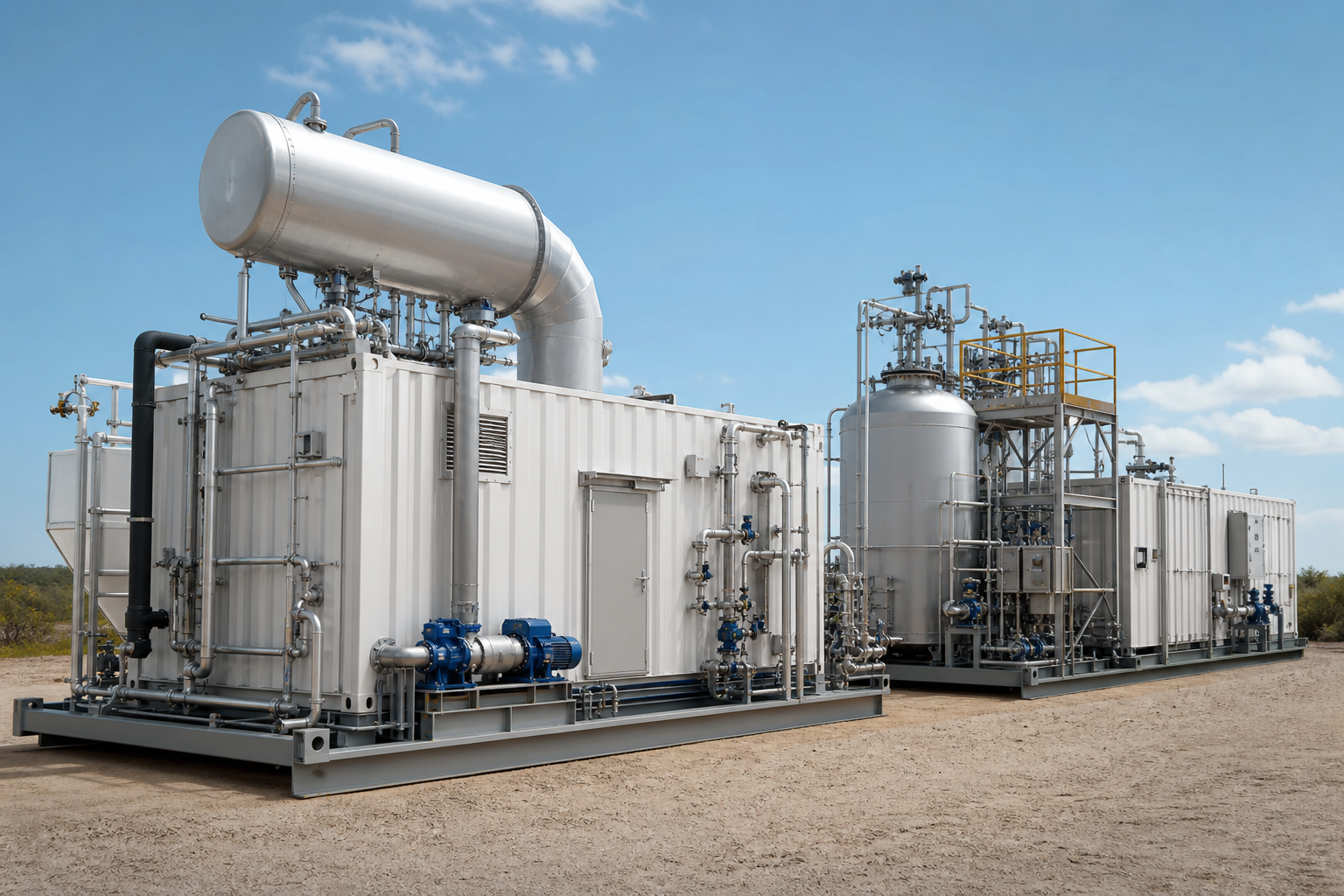
Scale dictates form factor. Single-well and CBM pads use integrated MVR units in standardized steps — 200 kg/h, 500 kg/h, 1 t/h, 2 t/h — factory-assembled, needing only power and water ties, with 10–15% load margin. Centralized gathering runs 5–20 t/d through 20–100 t/d to above 100 t/d, where the compressor shifts from Roots-type (below roughly 5 t/h) to centrifugal machines with wider flow range and longer service intervals. At the top, projects have been built at 1,000 m³/day flowback and 800,000 m³/year oilfield-water scale (published industry references), and skid-mounted zero-discharge evaporators have served gas purification plants. Offshore, compactness is the extra constraint: treating and returning water on-platform cuts disposal logistics and overboard discharge permitting. Packaged-unit details are on our skid-mounted and modular systems page.
Why the Disposal Alternatives Keep Getting Worse
The economics are set by the alternatives, and those keep deteriorating. Deep-well injection faces tightening permitting and induced-seismicity scrutiny, lengthening approvals and capping volumes precisely as fields age and water cuts rise. Trucking and haul-off scale with distance from disposal infrastructure, punishing remote pads hardest — the same pads where MVR skids install fastest. And in water-scarce regions, regulators increasingly frame produced water as a resource, with ZLD expectations spreading from coal chemical into oil and gas permitting. An operator showing 90%+ recovery with compliant solid salt negotiates permits from a different position than one proposing continued injection.
There is also a reliability argument that shows up in fleet operating data: suppliers serving this sector report equipment availability above 99% for installed evaporation systems (supplier-published; indicative), with maintenance concentrated in predictable compressor and heat-exchanger service rather than the crisis interventions that characterize overloaded pretreatment. The distinction matters for unmanned pads, where a water system that stops is a production system that stops.
Commissioning and Operating Discipline
Three habits separate smooth plants from troublesome ones. First, instrument the non-condensables: continuous venting with automatic release, because accumulated NCG silently erodes heat transfer before anything alarms. Second, schedule cleaning around water chemistry, not the calendar — high-hardness CBM feed demands more frequent cleaning than low-hardness flowback, and the antiscalant program should be tuned from early operating data. Third, watch compressor inlet temperature and vibration as the primary early-warning channel; on oily service, vapor-side cleanliness (demister and scrubber condition) is the real health indicator.
Startup deserves its own procedure: initial heat-up is the only phase consuming live steam, and sequencing vacuum, circulation pumps, and compressor load-up protects the rotor from thermal shock and the exchanger from dry-wall fouling. Plants that encode the sequence in the DCS once rarely revisit it; plants that improvise it annually own the consequences.
Water Reuse: Where the Value Accrues
The distillate is the product, and oil and gas operations consume a lot of it: recovered water returns to cooling towers, boiler feed after polishing, fracturing make-up, and dust control; in CBM applications it serves production spraying, equipment cooling, and road suppression. Field references report energy demand reductions up to 80% versus steam-driven evaporation and recovery of 90–95% in water-scarce onshore service, with disposal volumes and trucking falling accordingly. Combined multi-effect and MVR arrangements are also fielded where waste heat exists, and the underlying technology is described on our MVR evaporation page; the crystallizer end of the train follows the same salt-recovery logic as other ZLD applications, covered under zero liquid discharge.
When This Route May Not Fit
Evaporation competes with disposal, and where disposal is cheap it loses. Mature basins with permitted, low-cost injection wells and no seismicity scrutiny have little economic reason to evaporate. Low-salinity produced water that meets reuse standards after conventional treatment needs no evaporator. Near-saturated brines above roughly 250,000 mg/L push metallurgy and scaling economics past the practical window. Remote pads without reliable power — grid or generation — cannot run a compressor-driven train. And offshore facilities holding compliant overboard-discharge permits gain little until regulation closes that route.
What Must Be Verified
Verification starts with the water: full analysis across well history and season — TDS, chloride, hardness, silica, oil, and COD — because pretreatment depth, metallurgy tier, and cleaning cadence all hang on it. Second, pretreatment performance confirmed against the evaporator feed gates on the real stream. Third, softening depth against the scaling prediction for the concentration factor. Fourth, the chloride tier re-checked at maximum, not average, concentration. Fifth, turndown matched to documented flow swings, and the compressor type sized accordingly. Sixth, condensate quality against its named reuse consumer, and the salt disposal or recovery route.
FAQ
How much water does MVR evaporation recover from produced water?
Operating projects report 90–95% recovery as reusable distillate on high-salinity produced water in water-scarce onshore regions, with the balance leaving as crystallized salt and a small mother-liquor purge.
What pretreatment does produced water need before an MVR evaporator?
Free oil and solids by skimmer, API separator, or hydrocyclone; then coagulation-sedimentation, media filtration, and softening to reach roughly COD below 500 mg/L, SS below 10 mg/L, and controlled hardness and silica.
What materials are used for high-chloride produced water?
316L below about 1,000 mg/L chloride; 2205 duplex from 1,000–5,000 mg/L; titanium (TA2) above 5,000 mg/L or in weakly acidic service; Hastelloy for the most aggressive combinations.
How much energy does MVR evaporation use per ton of water?
Typically 15–30 kWh per ton evaporated on produced water and flowback duty — the basis for the sector’s reported energy reductions of up to 80% versus steam-driven evaporation.
Can MVR units work on remote well pads?
Yes. Integrated skid units in 200 kg/h to 2 t/h evaporation sizes ship factory-assembled, need only utility tie-ins, and ride through flow swings with 10–15% load margin and variable-frequency drives.
To screen this route, share the produced-water analysis, the flow and its swing range, and the reuse or discharge target — enough for an initial train-configuration assessment.