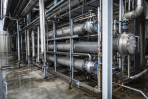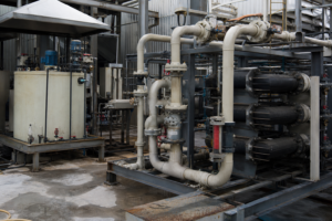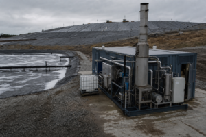
High-salinity wastewater — defined in practice as water bearing organic load and at least 3.5% total dissolved solids — defeats biological treatment and bankrupts physicochemical treatment, which is why evaporation and crystallization have become the default route to zero liquid discharge. A modern high-salinity ZLD train concentrates the brine in forced-circulation or falling-film evaporators, crystallizes the salt in an OSLO or DTB-type crystallizer, returns the mother liquor to the evaporator, and discharges condensate clean enough for reuse; where the feed carries mixed salts, ternary phase-diagram analysis separates it into individual by-product salts that can be sold rather than landfilled. This page lays out the full process chain, the selection logic, and the real performance numbers behind industrial systems.
What Counts as High-Salinity Wastewater, and Where It Comes From
High-salinity wastewater is generally defined as wastewater that contains organic matter and at least 3.5% TDS by mass, dominated by chloride, sulfate, sodium, and calcium ions. The 3.5% threshold is not arbitrary: above roughly seawater strength, conventional activated-sludge biology begins to lose efficiency because the osmotic stress inhibits the microbial community, and every percentage point of additional salinity narrows the biological treatment window further.
The feed sources cluster into two families. The first is coastal industry that uses seawater directly for cooling and process water, producing a continuous saline discharge. The second is process-generated brine: acid and alkaline wastewater from power and steel plants, flue-gas desulfurization wastewater, reverse-osmosis concentrate and ion-exchange regeneration liquor from chemical and pharmaceutical water systems, landfill leachate, oil and gas extraction produced water, and high-salt effluent from dairy processing and pickled-vegetable production. RO concentrate deserves particular attention — as more plants adopt membrane pretreatment to cut freshwater demand, the concentrate stream they generate is exactly the high-TDS feed that an evaporator must then finish.
Why Conventional Treatment Fails on High-Salt Streams
Biological methods fail first. The salt itself is the problem: above the inhibition threshold, microorganisms lose the ability to metabolize the organic fraction, so COD removal collapses regardless of reactor design. Physicochemical methods — advanced oxidation, coagulation, adsorption — can attack the organics but carry high investment and operating costs at brine strengths, and none of them remove the salt itself. The salinity has to go somewhere physical, and there are only two places: a membrane or an evaporator. Membranes hit osmotic-pressure walls and fouling limits near the top of the concentration range; thermal evaporation does not. This is why the industry consensus treatment for genuinely high-salt wastewater is evaporation followed by crystallization.
The Evaporation–Crystallization Route to Zero Liquid Discharge
The full process chain has six blocks: feed conditioning (pH adjustment, softening, and removal of scaling species such as calcium and magnesium), preheating using recovered vapor heat, concentration in a multiple-effect or MVR evaporator, crystallization of the saturated brine, solid–liquid separation in a centrifuge, and closed handling of the two outlet streams — wet salt and condensate. The design objective is that every water molecule leaves the system either as clean condensate or as crystal moisture, and every salt molecule leaves as by-product salt.
Mother-liquor management is what separates a true ZLD design from an evaporator with a crystallizer bolted on. The filtrate from the salt centrifuge carries dissolved salt and any accumulated impurities; in a closed design it is recycled entirely back to the evaporator circuit rather than purged, so impurities can only exit with the crystal phase. Full mother-liquor recycling plus 100% condensate reuse is the operating definition of ZLD at the evaporator level — anything purged is a discharge that needs a permit.
Viewed as equipment, the train decomposes into standard process modules:
| Process module | Equipment candidates | Selection basis | Indicative envelope |
|---|---|---|---|
| Feed conditioning | pH adjustment; softening; polishing filters | Scaling species (Ca, Mg) control | Per water analysis |
| Preheating | Plate exchangers on vapor and condensate | Heat recovery sets the steam economy | To the ~70°C class |
| Concentration | Multiple-effect or MVR evaporator | Local energy-price calculation | Published class: to 300,000 mg/L TDS |
| Crystallization | OSLO or DTB forced circulation | Crystal size and purity target | Published class: 0.5–1.5 mm |
| Solid-liquid separation | Centrifuge with full mother-liquor recycle | ZLD loop closure; yield | Published class: ≥95% yield |
| Salt handling | Closed wet-salt handling; dryer where sold | By-product salt specification | Per salt outlet |
Configuration, materials, and operating ranges for each module depend on the actual feed, temperature, pressure, corrosion review, fouling behavior, utilities, and project capacity.
Crystallizer Selection: Why OSLO and DTB Designs Dominate Salt Service
Salt crystallization is a particle-size business. Fine salt blinds centrifuges and filters, retains more mother liquor, and dries poorly; large uniform crystals wash clean, dewater to low moisture, and meet by-product salt specifications. That is why forced-circulation OSLO crystallizers — which separate the supersaturation zone from the crystal growth zone and fluidize the crystal bed — are the standard choice for industrial salt, and why suppliers publish indicative 20–30% higher capacity versus conventional forced-circulation designs at equal crystal quality – a supplier-published range, not a project guarantee. DTB (draft-tube baffle) crystallizers occupy the same niche where very tight crystal-size distribution matters, for example in pharmaceutical-grade or battery-grade salts.
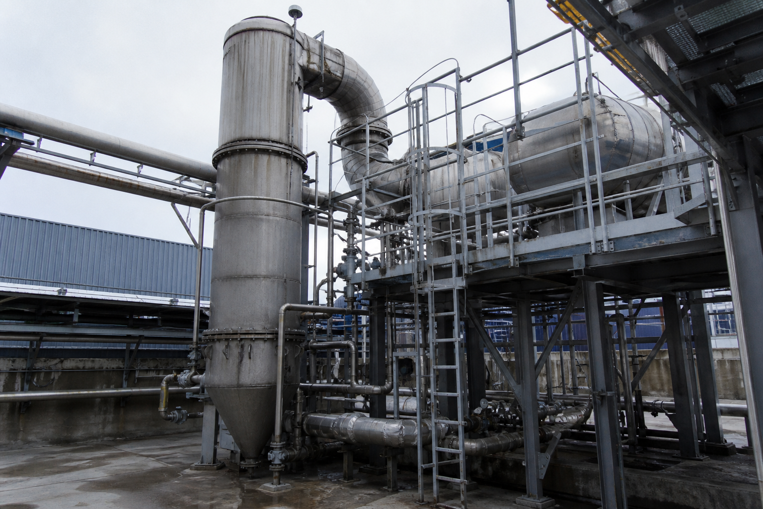
| Crystallizer type | Supersaturation mode | Typical crystal size | Best fit in high-salinity service |
|---|---|---|---|
| OSLO (forced external circulation) | Evaporative, generated away from the bed | 0.5 – 1.5 mm | Industrial NaCl / Na₂SO₄ recovery; large uniform crystals; low scaling risk |
| DTB (draft-tube baffle) | Evaporative with internal classification | Coarse, narrow distribution | High-purity salts; tight specification on particle distribution |
| Simple forced circulation | Evaporative, in-tube | Fine | Fouling slurries where crystal quality is secondary to uptime |
| Cooling / vacuum crystallizer | Cooling curve of the solubility diagram | System-dependent | Salt systems with strong temperature-dependent solubility (e.g. sulfate-bearing brines) |
Cooling is frequently used as a finishing step after evaporative saturation. In one published triple-effect design, brine reaches saturation in the third effect at about 70°C, the crystal slurry is then cooled to 40–45°C in a crystallization tank to harvest additional salt from the temperature-dependent solubility, and only then goes to the centrifuge — with the mother liquor recycled to the third effect. The cooling step converts residual dissolved salt into product that simple evaporation would leave in solution.
Salt Separation: Turning Mixed Salt into Individual By-Product Salts
The economic difference between hazardous mixed waste and sellable by-product salt is separation quality. Many industrial brines carry two or more salts simultaneously — sodium sulfate with sodium chloride, potassium chloride with sodium chloride — and crystallizing them together produces a mixed salt that in most jurisdictions is disposal-grade, not product-grade. The engineering answer is ternary phase-diagram analysis: by mapping the brine composition onto the Na₂SO₄–NaCl–H₂O (or KCl–NaCl–H₂O) system and applying the lever rule to determine phase ratios, the process designer schedules evaporation, flash, and cooling-freezing steps so each salt crystallizes in its own purity window.
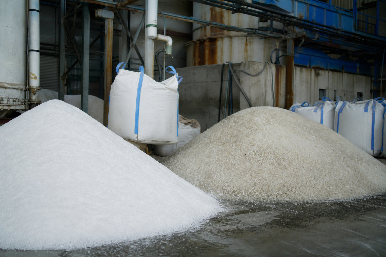
Recovered sodium chloride and sodium sulfate produced this way can meet national by-product salt standards and be sold or returned to industrial use directly — converting a hazardous-waste disposal cost into revenue. The same phase-diagram discipline also drives equipment selection: sulfate systems with retrograde solubility respond to cooling and freezing steps, chloride systems to straightforward evaporative crystallization. Our salt separation technology page details the process variants; the general architecture of a ZLD train is covered under zero liquid discharge solutions.
Reference Design: Triple-Effect Evaporator with OSLO Crystallizers
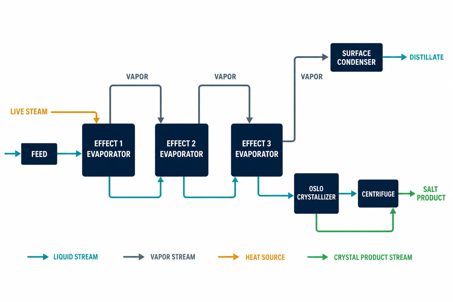
Supplier-published engineering data for a representative high-salinity system – an indicative range, not a project guarantee – shows what a fully specified design looks like. The plant processes 3,000 kg/h of 8% salt wastewater, evaporates 2,800 kg/h of water, and discharges 240 kg/h of wet salt at 8% moisture — a salt recovery so complete that the condensate is the only liquid leaving the plant. Concentration proceeds from 8% to the saturation point at 27.3%, where crystallization begins.
| Parameter | Value |
|---|---|
| Feed rate / salt content | 3,000 kg/h at 8% salt |
| Evaporation capacity | 2,800 kg/h |
| Wet salt production | 240 kg/h at ≤8% moisture |
| Steam consumption | 0.38 – 0.42 t per t of water evaporated |
| Power consumption | 18 – 22 kWh per t of water |
| Crystal size | 0.5 – 1.5 mm (adjustable) |
| Maximum brine TDS handled | 300,000 mg/L |
| Crystallization yield | ≥ 95% |
Three design details in this class of plant deserve attention. First, the flowsheet is parallel-flow triple-effect with OSLO forced-circulation crystallizers on the second and third effects — evaporation and crystallization happen in an integrated circuit, not sequential vessels. Second, feed preheating is two-stage heat recovery: third-effect vapor and first-effect condensate preheat the incoming feed to about 72°C, which is where the low steam consumption figure comes from; a plant that burns live steam on cold feed cannot reach 0.4 t/t. Third, control is PLC-based with automated regulation of temperature, pressure, and flow, because the crystal-size target — 0.5 to 1.5 mm — can only be held by steady supersaturation control, not by operator attention.
Case Evidence: Zinc Smelter Wastewater to Industrial-Grade Salt
As an external industry reference, the best-documented public proof point for high-salinity ZLD is the MVR evaporation-crystallization facility reported for Zijin Zinc Corporation, commissioned in October 2018 in published vendor case reporting. The plant owner — a smelter with 200,000 t/a zinc ingot and 400,000 t/a sulfuric acid capacity — had long treated its saline wastewater as an unsolved liability and, per the published account, entered the project with genuine doubts about MVR maturity. The reported commissioning outcome: sodium chloride crystal salt discharged continuously from the crystallizer, condensate COD at 4.5 ppm, and recovered NaCl meeting the national industrial salt standard, replacing disposal with by-product revenue. These are vendor-reported figures — an indicative range for the duty class, not a project guarantee and not a statement of EvapCryst delivery experience.
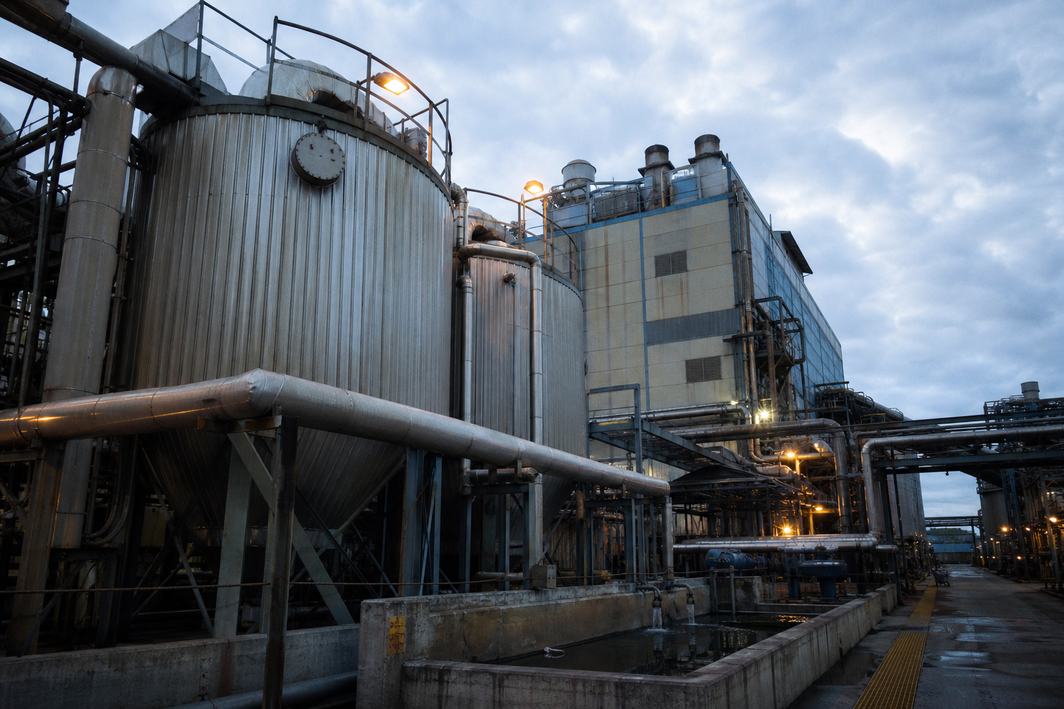
The 4.5 ppm condensate COD figure matters beyond this one plant. It demonstrates that in a properly designed evaporator the volatile organics that plague membrane concentrates do not carry over significantly into the condensate — water quality from thermal separation is set by entrainment design and de-entrainment hardware, not by the organic load of the feed. For plants weighing MVR against further membrane stages, condensate quality of this order is the baseline expectation, not the best case. The energy mechanics behind such systems are covered on the MVR evaporation page.
Materials, Modularization, and Sizing
Chloride brines at evaporating temperatures are among the most corrosive fluids in process industry, and material selection is the main hidden cost driver. Wetted parts in chloride service are specified in titanium or 2205 duplex stainless steel; sulfate-dominated systems tolerate standard stainless grades at lower cost. Getting this wrong does not fail the process — it fails the schedule, six months into operation, as a heat-exchange tube perforates.
On sizing, the market now offers skid-mounted modular MVR evaporators in standard capacities of 0.5, 1, 2, 5, and 10 t/h evaporation, which shortens delivery and commissioning for small and medium streams; larger duties remain stick-built. Multiple-effect steam systems such as the 3,000 kg/h design above occupy the middle ground where steam is available and electricity is expensive. The choice between MVR and multi-effect is an energy-price calculation, not a process preference: compare the multiple-effect steam economy against MVR electrical consumption using your local utility tariffs before committing. Mining-plant applications with similar high-TDS, high-COD feeds are discussed in our mining water treatment and zero discharge article.
When This Route May Not Fit
Below roughly 3.5% TDS this machinery is overkill: conventional biology still works, and the evaporator cannot pay for itself on a dilute stream. Small salt loads with an inexpensive disposal or deep-well option are cheaper to haul than to crystallize. Feeds dominated by volatile organics need oxidation pretreatment first, because the condensate – not the salt – becomes the quality bottleneck. Mixed-salt brines whose salts cannot be separated economically, and whose mixed cake is classified hazardous with no outlet, turn the project into an expensive way to make landfill. And sites with cheap steam, expensive electricity, and modest throughput sit exactly where multiple-effect, not MVR, is the honest recommendation.
What Must Be Verified
Before this route is committed, verify the inputs that size it. First, a complete water analysis: TDS, ionic composition, COD, ammonia, hardness, and silica, because scaling chemistry and materials selection hang on the details. Second, for mixed salts, a phase-diagram study confirming that separation into sellable single salts is feasible at the actual composition. Third, pilot or vendor data on scaling rate and crystal habit at the expected concentration, which sets cleaning intervals and crystal yield. Fourth, the regulatory position: condensate reuse standard, salt classification, and disposal limits in the specific jurisdiction. Fifth, the energy pair – steam and electricity prices with annual hours – which decides MVR versus multi-effect before any equipment is quoted.
Frequently Asked Questions
What is considered high-salinity wastewater?
Wastewater containing organic matter and at least 3.5% total dissolved solids by mass, dominated by chloride, sulfate, sodium, and calcium. Above this level — roughly seawater strength — biological treatment loses efficiency due to microbial inhibition, which is why thermal methods take over.
How does an evaporator-crystallizer ZLD system achieve zero discharge?
By closing both loops. All water leaves as condensate engineered for reuse, all salt leaves as centrifuge-discharged crystal, and the centrifuge mother liquor is fully recycled to the evaporator instead of being purged. With no liquid purge, the plant has no liquid discharge point — the operating definition of ZLD.
What steam and power consumption should a salt crystallization system achieve?
A well-designed triple-effect system with two-stage feed preheating runs at 0.38–0.42 t of steam per ton of water evaporated and 18–22 kWh of electricity per ton. MVR systems shift the balance to electricity by recompressing vapor, trading steam supply for power cost. Plants burning live steam on cold feed will miss these figures.
Can mixed salt wastewater be separated into sellable products?
Yes. Ternary phase-diagram analysis of systems such as Na₂SO₄–NaCl–H₂O, combined with the lever rule for phase ratios, schedules evaporation, flash, and cooling/freezing steps so each salt crystallizes in its own window. Recovered NaCl and Na₂SO₄ can meet national by-product salt standards and be sold rather than disposed of as hazardous waste.
What crystal size and salt quality can be achieved?
OSLO forced-circulation crystallizers routinely produce 0.5–1.5 mm industrial salt at ≥95% crystallization yield and ≤8% centrifuge moisture. In the published Zijin Zinc reference case, the recovered sodium chloride met the national industrial salt standard and condensate COD was 4.5 ppm.
To screen this route for a specific brine, share the water analysis, the flow rate, and the reuse or discharge target – enough for an initial process-direction assessment.