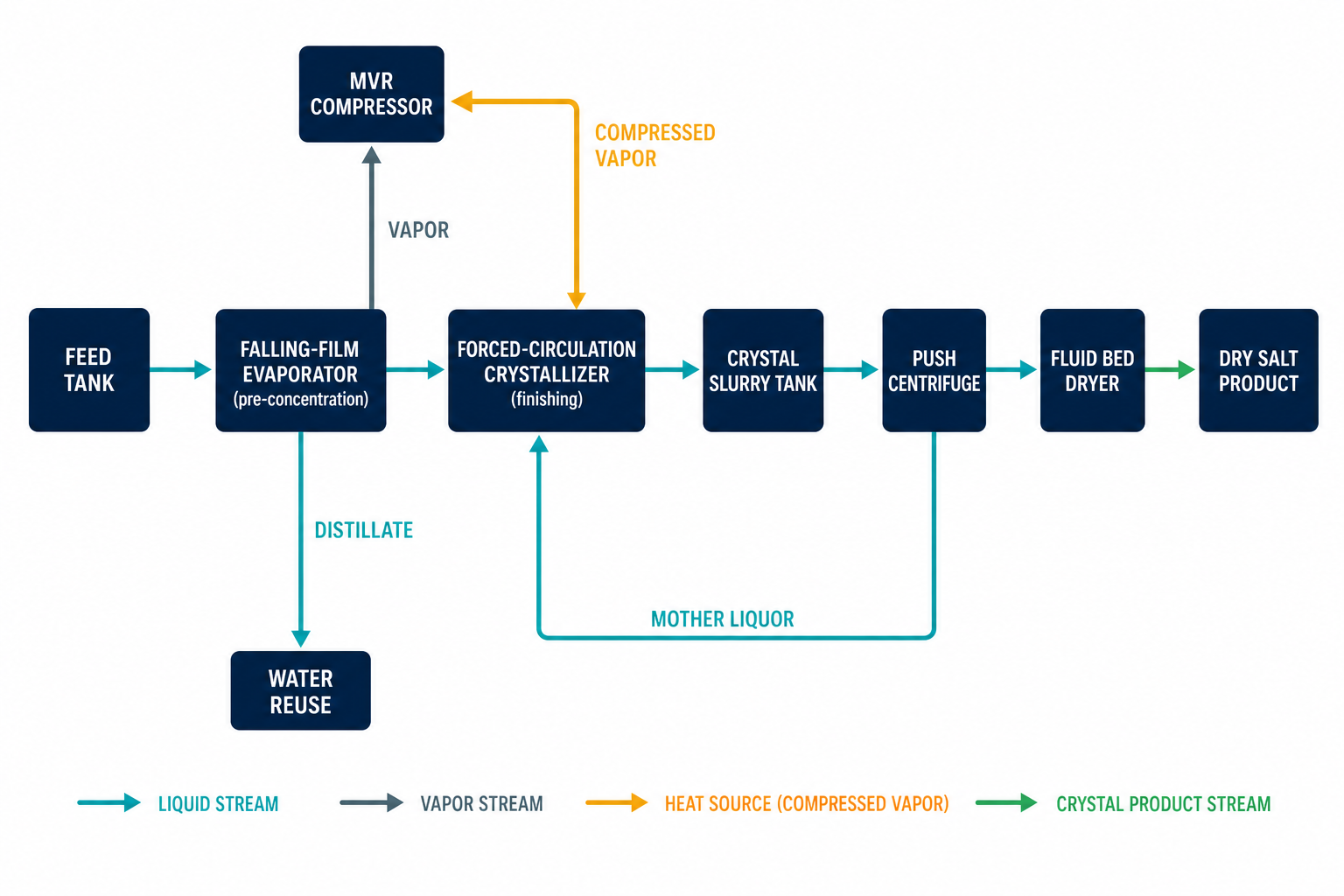
Process flow design for an evaporation plant is decided by three inputs — feed characteristics, process requirements, and site utility constraints — and in practice it comes down to choosing how the main evaporator bodies are arranged in series and parallel. For the majority of high-salinity and crystallizing duties, the widely adopted answer is a two-stage combination: falling-film pre-concentration followed by forced-circulation finishing, with mechanical vapour recompression (MVR) as the heat engine. This guide walks through the inputs, the balance calculations, the three mainstream flow sheet combinations, MVR design principles, temperature-difference allocation, materials selection, and how the process flow diagram (PFD) is carried into 3D coordinated engineering.
The Three Inputs That Determine the Flow Sheet
Before any equipment is sized, the designer must fix three categories of input conditions. First, feed characteristics: inlet concentration and target concentration, viscosity across the concentration range (typically 5-450 cp for film evaporator duties), thermal sensitivity of the product, and the crystallization or fouling tendency of the liquor. Second, process requirements: the concentration ratio, the required form of the final salt (slurry, crystals, or dry solid), and product purity targets. Third, site and utility constraints: available steam pressure, electricity price and capacity, cooling water temperature, plot space, and ceiling height.
These three input groups interact. A viscous, scaling-prone liquor pushes the design toward forced circulation; a heat-sensitive extract pushes it toward low-temperature falling film under vacuum; a site with expensive steam and cheap electricity pushes it toward MVR evaporation. No single flow sheet fits all three inputs at once — which is why flow sheet selection is always the first engineering decision, not an afterthought.
Start With Material and Energy Balances
Flow sheet selection is validated by two calculations before anything is specified. The overall material balance gives the evaporation duty directly from concentrations: for a feed rate F with solids (or salt) mass fraction x0 concentrated to x1, the water evaporated is W = F × (1 − x0/x1). This single expression determines evaporator capacity, compressor sizing, and downstream crystal handling, so it should be computed across the full expected feed-composition range, not just the design point.
The energy balance then converts W into heat load: Q = W × λ (latent heat at the operating temperature) plus sensible heat to bring the feed to its boiling point, minus recovered preheat. Required heat-transfer area follows from A = Q / (U × ΔT), where the overall coefficient U degrades as viscosity and fouling increase along the concentration path. Note that U is not constant along a falling-film calandria handling a saturating liquor — the terminal zone where crystals nucleate can run at a fraction of the inlet-zone coefficient, which is precisely why many flow sheets split the duty between a film evaporator and a separate forced-circulation finisher.
Three Proven Flow Sheet Combinations
Falling-Film Pre-concentration + Forced-Circulation Finishing
The most common MVR arrangement pairs a falling-film body for the bulk water removal with a forced-circulation (FC) body where salt is actually crystallized. The falling-film section contributes high heat-transfer efficiency at low temperature difference for feeds typically in the 5-450 cp range, while the FC section provides the high tube velocity and boiling suppression needed to discharge salt without plugging. Because the film section does the heavy lifting, the circulation rate through the crystallizer — and the pumping power that goes with it — can be kept low, which is where the energy advantage of this split comes from. The falling-film evaporator and forced-circulation evaporator pages detail each body’s operating window.
All Forced Circulation
When the feed is already near saturation, prone to crystallization on any heat-transfer surface, or inclined to foam, the whole duty is placed in forced circulation. This flow sheet is the workhorse of high-salinity wastewater and zero liquid discharge (ZLD) trains (illustrative application), where its resistance to scaling outweighs its higher specific pumping power and larger heat-transfer area per tonne of water removed.
Rising Film + Forced Circulation
A rising-film (climbing-film) pre-concentration stage ahead of FC finishing suits large-volume, heat-sensitive liquors such as traditional Chinese medicine extracts and similar botanical concentrates (illustrative applications). The rising-film body requires the feed to enter at or very close to its evaporation temperature, so this combination always includes a dedicated feed preheating train — the same preheating that later serves the energy balance.
| Flow sheet combination | Best-suited feed | Division of duties | Key design note |
|---|---|---|---|
| Falling film + forced circulation | Low-to-medium viscosity (approx. 5-450 cp), moderate scaling | Film body concentrates efficiently; FC body crystallizes and discharges salt | Lower crystallizer circulation rate = lower pump power; the most common MVR layout |
| All forced circulation | Near-saturated, crystallizing, foaming liquors; high-salinity wastewater | All evaporation and crystallization in FC bodies | Strongest anti-scaling robustness; budget for higher pumping power and area |
| Rising film + forced circulation | Large-volume concentrates, heat-sensitive extracts (e.g. herbal/botanical) | Rising film pre-concentrates; FC finishes | Feed must be preheated to evaporation temperature before the rising-film body |
MVR System Design: Three Principles and Five Tasks
Once MVR is chosen as the vapour-side driver, three design principles govern the process flow. First, minimize and eliminate feed supersaturation spikes at the evaporating surface: crystals need a stable, moderate supersaturation field to grow well, so circulation rates, boiling-point elevation, and the point where salt is introduced must be arranged to give crystals a favourable growth environment rather than nucleation shocks. Second, eliminate short-circuit temperature losses between stages: routing that allows hot feed to shortcut into a colder body destroys the flash-evaporation and vapour-liquid separation logic and increases entrainment, so inter-stage piping and seal arrangements must preserve the designed temperature ladder. Third, keep evaporator internal surfaces smooth and clean: polished welds, elimination of dead zones, and correct velocity distribution prevent salt from adhering and lumping, which is a leading cause of forced shutdown.
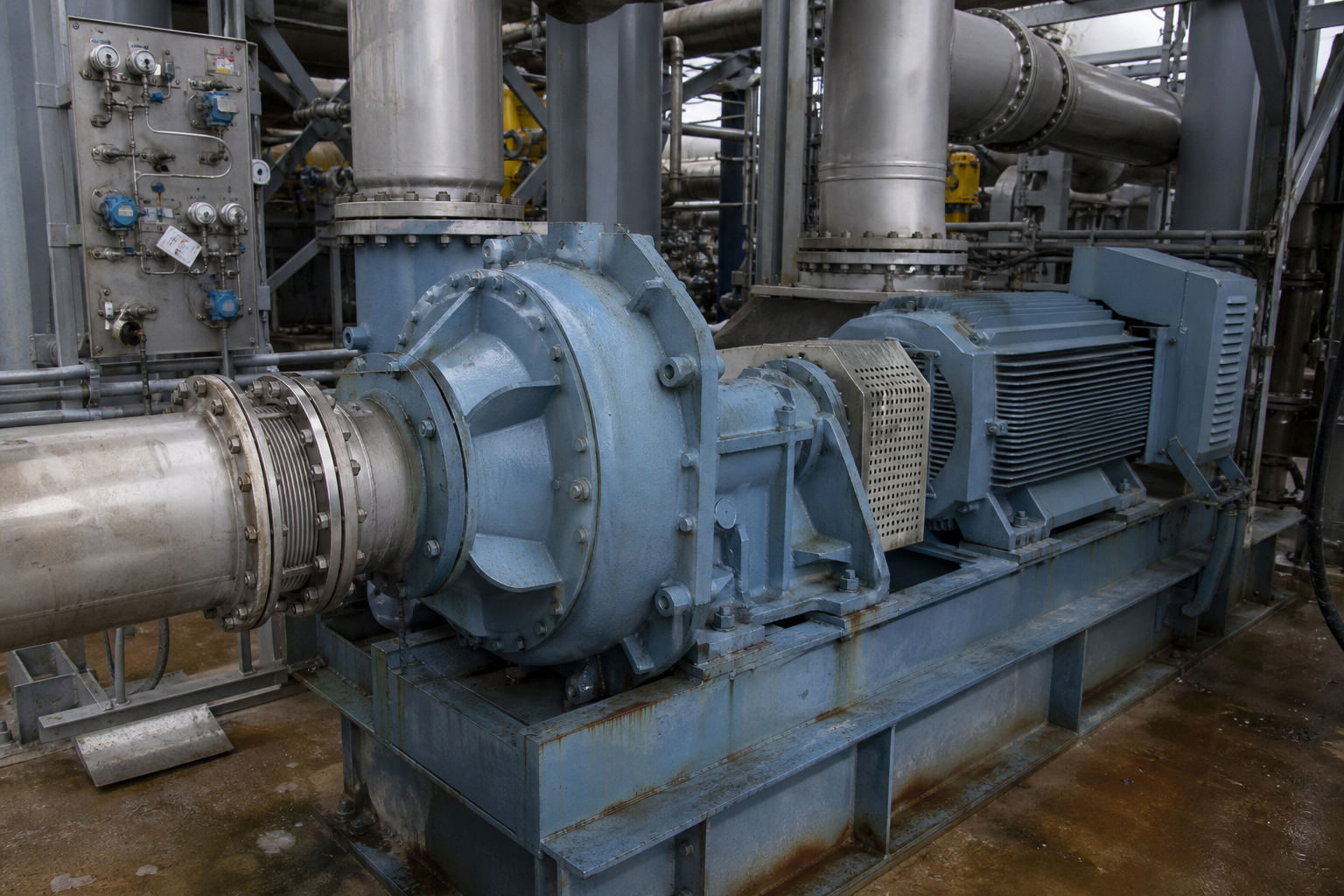
Translating the flow sheet into hardware then comes down to five core tasks: compressor selection (type, stage count, and material), evaporator heat-transfer area calculation, materials selection for every wetted part, auxiliary equipment selection (pumps, preheaters, condensers, vacuum system, non-condensable extraction), and the automation and control system design. Each task feeds back into the others — for example, a compressor with a modest temperature lift forces a larger heat-transfer area, while a highly scaling liquor forces both materials and control philosophy.
Temperature-Difference Allocation and Feed Preheating
In multi-effect trains, the total available temperature difference is defined as the span between the maximum permissible heating temperature in the first effect and the lowest boiling point in the last effect, and it must be allocated effect by effect. Each effect’s driving force equals its allocated difference minus that effect’s boiling-point elevation (BPE). As the number of effects grows, the difference available per effect shrinks, so per-effect heat-transfer area must grow — the classical economic trade that usually caps salinity duty plants at three, at most four, effects.
Feed preheating deserves explicit design attention in every flow sheet, whatever the vapour side. Condensate and distillate still leave the plant hot, and a preheat train — feed successively against distillate, then condensate, then (if present) live steam trim — recovers this sensible heat, bringing the feed to near its boiling point before the first evaporating surface. Done well, the preheat ladder removes most of the sensible-heat load from the evaporator bodies themselves, shrinking both area and energy demand; done badly, the same heat is rejected to cooling water and paid for twice.
Materials Selection Driven by Chloride and pH
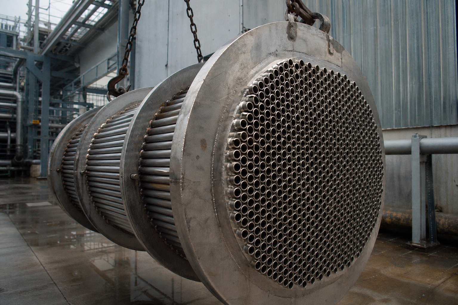
Wetted materials are a process-flow-design decision, not a procurement afterthought, because chloride concentration and pH change along the concentration path — the most corrosive point is usually deep in the train, not at the feed. As a common industry guideline for chloride-bearing liquors: below roughly 100 ppm chloride, SS304/316L is generally adequate; from about 100-5,000 ppm, duplex 2205/2507 is the safer choice; above roughly 5,000 ppm or at low pH, titanium (TA2/Gr.2) or Hastelloy grades are typically specified. BPE, velocity, and temperature all shift these boundaries, so final selection should be confirmed against lab corrosion data for the actual liquor. A fuller discussion is in the construction materials and corrosion protection guide.
| Liquor condition (guideline) | Typical material class | Relative cost indication |
|---|---|---|
| Chloride < ~100 ppm, neutral pH | SS304 / 316L | Baseline (1.0×) |
| Chloride ~100-5,000 ppm | Duplex 2205 / 2507 | Approx. 1.6-2.2× |
| Chloride > ~5,000 ppm, high acid or oxidizing | Titanium TA2/Gr.2, Hastelloy C-family | Approx. 3.5-5.0× |
From PFD to P&ID to 3D Coordinated Engineering
Two drawings carry the design forward, and they answer different questions. The PFD (process flow diagram) shows the functional flow — bodies, compressor, preheaters, separators, pumps — with major stream data, and is the tool for process decisions like those above. The P&ID (piping and instrumentation diagram) adds every line, valve, spec break, and instrument loop, and is the tool for procurement, HAZOP, and construction. Evaporation projects typically iterate PFD first until the balance and combination are frozen, then develop P&IDs per area as the design matures.

On the physical side, 3D plant design has replaced the traditional drawing-by-drawing handoff between disciplines. Process piping, structure, layout, civil, and electrical teams work in one shared model, which delivers eight practical advantages: multi-discipline collaboration on the model as the deliverable, with clash checks run continuously rather than at reviews; structural drawings converted 1:1 into the 3D model so structural data lives in one place; direct visual checking of maintenance access around every equipment item; verification of equipment dimensions against steelwork before fabrication; reconciliation of civil foundations with equipment anchor points; cable-tray routing and elevation adjusted around clashes before installation; a single parametric source for construction queries; and genuinely parallel discipline design that replaces the slow, error-prone inter-discipline “drawing transmittal” loop. The practical result reported in published project retrospectives (external industry references) is fewer site reworks, shorter design-to-delivery cycles, and higher design correctness — benefits that compound on skid-mounted and modular builds where shop fabrication tolerances are tight.
Frequently Asked Questions
How do I choose between falling film and forced circulation in the flow sheet?
Use falling film for the bulk evaporation of low-to-medium viscosity feeds (roughly 5-450 cp) where thermal efficiency matters; use forced circulation where the liquor is near saturation, scaling, or foaming. Most crystallizing plants use both: film first, forced circulation last, so salt only meets a surface designed to tolerate it.
What is the difference between a PFD and a P&ID in an evaporation project?
A PFD shows the process logic — main equipment, major streams, and key operating data — and is used to freeze the process design. A P&ID adds all piping, valves, and instrument loops and is used for procurement, safety review, and construction. PFDs are iterated early; P&IDs develop per area afterward.
Why does MVR design emphasize supersaturation control?
Crystal quality and stable operation both depend on keeping supersaturation moderate and steady. Supersaturation spikes cause nucleation showers that produce fine, uneven crystals and deposit salt on heat-transfer surfaces — the main path from a badly designed flow sheet to unplanned shutdowns.
How is stainless steel chosen for chloride-bearing liquors?
As a guideline, SS304/316L suits chloride levels below about 100 ppm; duplex 2205/2507 covers roughly 100-5,000 ppm; titanium or Hastelloy is specified above about 5,000 ppm or in strongly acidic media. Confirm the boundary with corrosion testing on the actual liquor, since pH, temperature, and velocity all matter.