MVR (mechanical vapor recompression) evaporation works by capturing the secondary vapor released from boiling liquid, mechanically compressing it to a higher pressure and temperature, and returning it to the heat exchanger as the heating medium for the same liquid — recycling the latent heat of vaporization in a closed loop. In steady operation a typical system consumes 15–30 kWh of electricity per tonne of evaporated water on clean low-BPE feeds and 30–50 kWh on high-BPE chemical brines, instead of burning live steam, with typical savings of 70–90% versus single-effect evaporation and 50–80% versus thermal vapor recompression. This page is the technology deep-dive — thermodynamics, the nine core components, the design parameters that decide success or failure; for system configurations, delivery models and documented application results, see our MVR evaporation systems page.
The Thermodynamic Essence: Upgrading Waste Heat with Shaft Work
Every kilogram of water evaporated carries roughly 2,260 kJ of latent heat. In a conventional evaporator that heat leaves the system as low-pressure secondary vapor and is lost to a condenser. The vapor is thermodynamically “hot” enough to boil more liquid, but it is a few degrees too cold and a few kilopascals too low in pressure to serve as heating medium for the very liquor it came from.
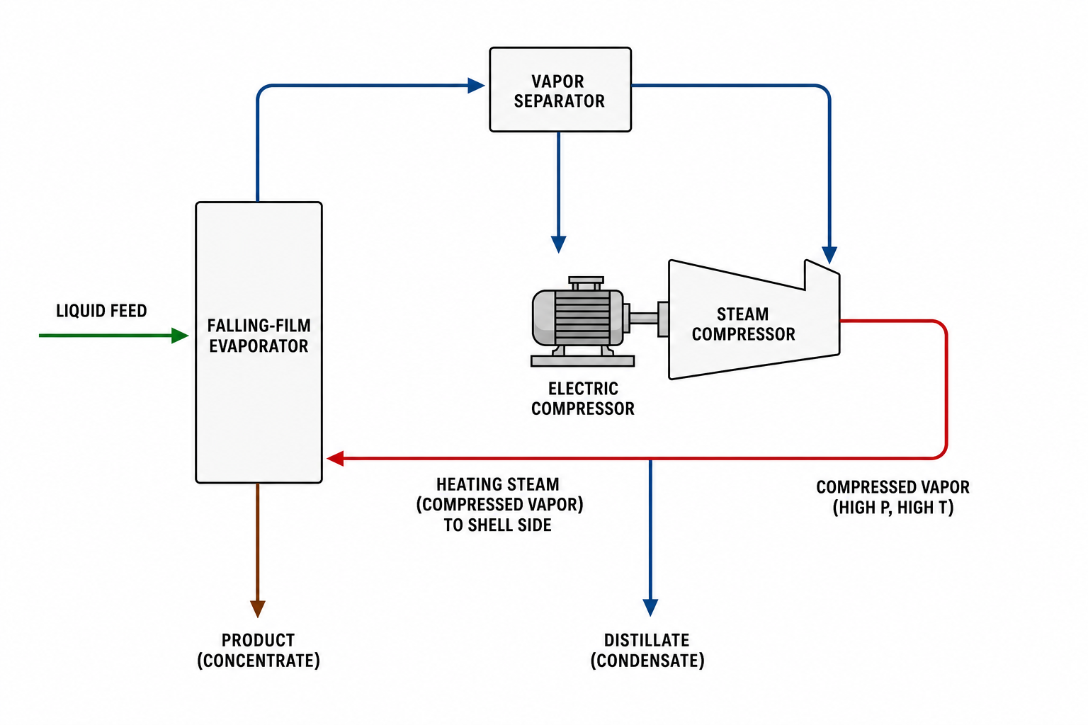
An MVR system closes this gap with a mechanical compressor. Compression raises the vapor’s pressure, temperature, and enthalpy — typically by just enough to create a small useful temperature difference across the heat exchanger. The upgraded vapor condenses inside the heater, releasing its latent heat to evaporate more liquid, and the condensate leaves as hot process water. The only significant energy input is the compressor shaft work, which is why electricity, not steam, becomes the plant’s evaporation currency. As a result, MVR heat performance is often described in industry literature as equivalent to a 20–30 effect multi-effect evaporator, while the process flow is far simpler and more compact.
The Working Cycle, Step by Step
- Thin-film or circulating liquor boils in the evaporator body under a controlled vacuum or slight pressure.
- Secondary vapor is drawn off and passes through a separator/demister that removes entrained droplets.
- A mechanical compressor (roots, centrifugal, or axial) compresses the vapor, raising its saturation temperature.
- The compressed vapor condenses in the heat exchanger, transferring latent heat to the evaporating liquor.
- Condensate is collected in the condensate tank; concentrated liquor circulates or is drawn off to the crystallizer.
- The loop repeats — energy circulates inside the system instead of being exhausted.
External steam is needed only for start-up, when a small boiler charge preheats the system to boiling. Once the compressor is on-line and the heat balance closes, the plant runs on electricity with at most minor steam make-up.
Nine Core Components and What Each One Does
| Component | Function | Why it matters |
|---|---|---|
| Steam compressor | Raises secondary vapor pressure and temperature | The heart of the system; sets the achievable temperature lift |
| Heat exchanger (calandria) | Transfers latent heat from compressed vapor to liquor | Area must be sized with a 1.1–1.3 fouling safety factor |
| Vapor-liquid separator | Disengages liquid from vapor | Protects product purity and downstream equipment |
| Secondary separator (demister) | Removes entrained droplets before the compressor | Key to compressor lifetime — droplets erode impellers and rotors |
| Thickener (crystallization stage) | Cools and drives supersaturation for crystal growth | Turns concentrated liquor into dischargeable crystal slurry |
| Condensate tank | Collects clean hot condensate | Condensate recovery adds a further 5–10% energy benefit |
| Centrifuge | Separates crystals from mother liquor | Solid-liquid split after crystallization |
| Mother liquor tank | Buffers recycle liquor | Maintains steady composition at the evaporator inlet |
| Circulation pump | Moves liquor through the heater at design velocity | Sustains heat transfer and suppresses wall fouling |
A full system also includes the vacuum unit, non-condensable gas venting, and a PLC-based automation package; together these nine-plus components define the mechanical scope that suppliers quote against.
Start-up Versus Steady State
A frequent misconception is that an MVR plant still needs a steam boiler. In reality, steam is consumed only during the start-up phase to preheat feed and equipment to operating temperature. At steady state, live steam demand approaches zero — the compressor supplies the temperature lift, and the system’s heat losses are covered by sensible heat in the feed. This makes MVR especially attractive on sites with no boiler, limited boiler capacity, or unreliable fuel logistics.
Energy Performance: The Numbers
Indicative figures published by equipment suppliers — external industry references, not project guarantees — fall in these ranges:
- Electricity: typically 15–30 kWh per tonne of evaporated water on clean low-BPE feeds; 30–50 kWh on high-BPE chemical brines (site-wide caliber used across this site).
- Versus single-effect: 70–90% energy savings; steam consumption cut by more than 70% in externally reported cases where evaporation energy accounted for 20–30% of total production cost.
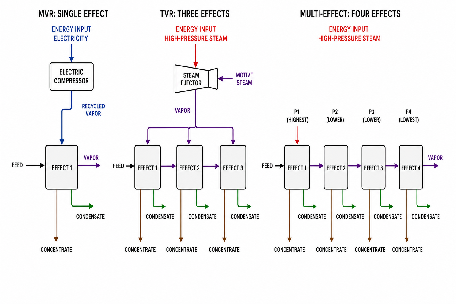
- Versus TVR: 50–80% savings, because TVR re-compresses only part of the secondary vapor using motive steam, while MVR recirculates all of it.
- Cooling water: reductions of 90% or more, since the heating side itself acts as the condenser and recovers the latent heat.
- Payback: typically 1.5–3 years against conventional evaporation, versus more than 5 years for traditional systems in comparable duty.
Site-specific results depend on electricity tariffs, steam prices, and annual operating hours — the comparison is best made with the actual utility prices, as this site’s energy comparison tool is designed to do.
Design Parameter 1: Temperature Difference (3–8 °C)
The heat exchanger is designed for a small effective temperature difference, typically 3–8 °C between the condensing compressed vapor and the boiling liquor. This is a deliberate compromise: a larger ΔT would require more compressor work (energy cost) and higher wall temperatures (product quality risk); a smaller ΔT would demand excessive heat-transfer area (capital cost). For heat-sensitive products the low ΔT is an advantage — it eliminates local overheating and the color/degradation issues that come with it.
Design Parameter 2: Compressor Type and Compression Ratio
Three compressor families cover the market:
- Roots (positive displacement): robust, economical for small-to-medium vapor flows and moderate lifts.
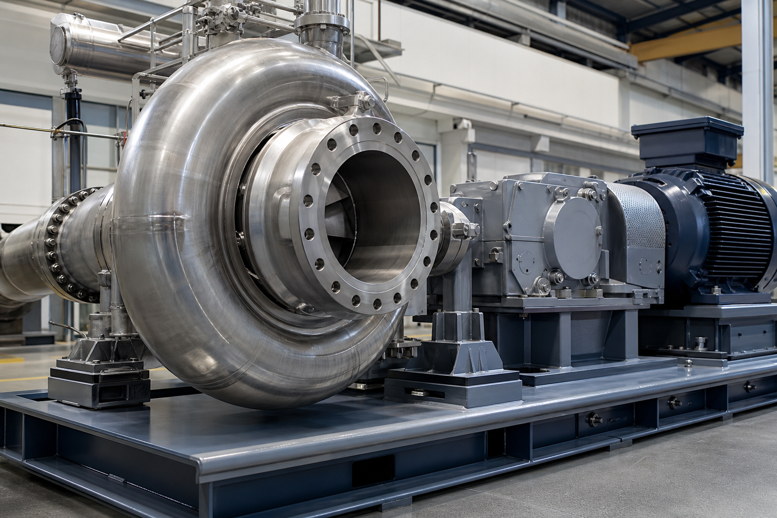
- Centrifugal: the workhorse for medium-to-large capacities; high speed, oil-free designs available.
- Axial: very large flows where staging keeps power consumption reasonable.
Across all types, compression ratios above about 2.0 are a warning zone: they increase power consumption disproportionately and shorten equipment life. Well-designed systems therefore combine a modest compression ratio with generous heat-transfer area, and protect the compressor with the demister and, where needed, liquid-ring or dry-seal arrangements.
Negative-Pressure (Low-Temperature) MVR
Combining MVR with a vacuum system is the standard answer for heat-sensitive feeds. Under negative pressure the liquor’s boiling point drops sharply, so evaporation completes in a gentle 40–60 °C window — far below the 70–100 °C of conventional atmospheric evaporation. Three benefits follow:
- Product protection: no thermal degradation of active ingredients, colors, or aromas — decisive for food extracts, enzymes, and pharmaceutical intermediates.
- Slower fouling: lower wall temperatures and reduced crystallization rates mean less scale formation, longer runs, and fewer cleanings.
- Compact energy loop: the vacuum system maintains the set boiling temperature while the MVR unit recovers the latent heat, and PLC control monitors negative pressure, evaporation temperature, and vapor pressure in real time.
This dual “low-temperature evaporation + energy recovery” architecture is what makes MVR practical in quality-critical industries from food processing to biotechnology.
MVR vs TVR vs Multi-Effect Evaporation
The architecture comparison — energy source, share of secondary vapor recompressed, equivalent-effect count, capital, maintenance and footprint across MVR, TVR and multi-effect — lives in two dedicated pages rather than being repeated here: the MVR systems page carries the when-each-wins decision table with documented results, and MVR evaporator selection walks through the full decision process. In one line: MVR wins where electricity is available and affordable and steam is expensive; TVR wins where steam is cheap and simplicity matters; MEE remains reasonable for very small scale or short-project horizons.
Automation and Control
Modern MVR plants are configured for continuous, lightly staffed operation. PLC systems with HMI touch screens and remote login monitor vacuum, temperature, and pressure continuously, adjusting feed rate, compressor speed, and venting automatically. One particularly valuable technique is tracking the dynamic overall heat-transfer coefficient (U-value): as fouling accumulates, U falls along a predictable curve, allowing the control system to forecast the next CIP (clean-in-place) cycle instead of waiting for throughput to collapse.
Fouling Management: The 1 mm Rule
Design practice for fouling services is concrete: heat-exchange area carries a 1.1–1.3 safety factor, and operators plan CIP around the measured performance decline. The reason is a rule of thumb widely cited in heat-exchanger design literature: a 1 mm scale layer reduces heat-transfer efficiency by roughly 10%. Feeds with total solids above roughly 30% or viscosities above roughly 1000 mPa·s accelerate fouling and depress evaporation rates, so they are either pretreated or moved to forced-circulation configurations where circulation velocity scours the surfaces.
Application Map
MVR duty spans battery and new-energy materials (lithium, nickel, cobalt, manganese salt recovery; LFP and ternary-precursor wastewater), pharmaceutical and fine chemicals, food and fermentation (see the threonine broth solution as an illustrative application), and water and waste — RO reject, landfill leachate, FGD wastewater and full ZLD trains. The documented results per industry — Jiangsu chemical-park ZLD, soy-salt recovery, coal-chemical Glauber’s salt lines — are collected with figures in the MVR systems page applications section, and are not repeated in this technology deep-dive.
Honest Limitations
MVR is not a universal replacement for evaporation:
- Capital: publicly quoted system prices typically run USD 0.3–1.5 million depending on capacity and materials — indicative ranges, not project quotations — materially higher than single-effect alternatives.
- Scale: for very small duties or short project lives, multi-effect evaporation can remain the more economical choice, a point also acknowledged in supplier FAQ material — indicative guidance, not a project conclusion.
- Power dependence: the plant runs on electricity; unreliable grids demand backup generation or hybrid steam capability.
Water and Carbon Footprint
Two closing benefits round out the case. Condensate recovery — routing clean hot condensate back into process water duties — adds a further 5–10% to the energy advantage. And because the system eliminates most on-site steam generation for evaporation, its CO2 footprint is lower than steam-driven alternatives; an externally reported mining-wastewater case study (public industry reference, not an EvapCryst project) saved roughly 710 tonnes of coal and about 2,478 tonnes of CO2 per year at 5.1 t/h capacity. For plants under carbon or water constraints, these figures often carry the investment decision. The energy retrofit and decarbonization overview covers how such conversions are scoped, as an illustrative application.
Frequently Asked Questions
Does an MVR evaporator need steam to run?
Only for start-up. External steam preheats the system to boiling; once the compressor is running, the closed loop recycles the latent heat of the secondary vapor and the plant operates on electricity with minimal or no live steam.
How much energy does MVR save compared with conventional evaporation?
Typical figures are 15–30 kWh of electricity per tonne of evaporated water on low-BPE feeds (30–50 kWh on high-BPE brines), 70–90% energy savings versus single-effect evaporation, and 50–80% versus TVR. Heat performance is often described as equivalent to a 20–30 effect multi-effect evaporator.
Why keep the temperature difference so small (3–8 °C)?
A small ΔT balances compressor power against heat-transfer area. Pushing it higher wastes electricity and risks overheating the product; shrinking it inflates capital cost. The narrow band also produces gentle, uniform heating valued in heat-sensitive duties.
What is the role of the secondary separator?
The secondary separator (demister) removes entrained liquid droplets from the secondary vapor before it enters the compressor. Clean vapor is essential: droplets erode compressor internals and are the single most common cause of premature compressor failure.
Can MVR handle heat-sensitive products?
Yes. Negative-pressure MVR lowers the boiling point so evaporation proceeds at roughly 40–60 °C with small, uniform temperature differences and no local overheating — preserving actives, colors, and flavors in food, enzyme, and pharmaceutical applications.