For optical fiber plants that capture chloride-bearing dust from fiber draw and quench operations with wet scrubbers, the workable zero liquid discharge (ZLD) route is a two-block system: chemical softening with tubular membrane filtration (TMF) to strip silica and hardness before they reach the evaporator, followed by a mechanical vapor recompression (MVR) train that splits the water into reusable distillate and a dewatered salt cake. The design premise is that only a small sidestream of the scrubbing loop – not the full flow – carries the salt load to the ZLD island, which keeps both capital and operating cost proportionate to the salt actually generated.
Where the Salt Comes From and Why Conventional Pretreatment Is Not Enough
Optical fiber production generates chloride-laden dust in the preform handling, drawing and surface treatment stages. Wet scrubbers collect this dust reliably, but every gram of chloride captured in the scrubbing liquor stays in the water. A supplier-published case description of one such plant reports a dissolved salt content of about 6.9% by mass in the scrubbing wastewater, dominated by chlorides, together with significant suspended silica (a supplier-published project reference – an external industry reference, not an EvapCryst delivery).
Plants typically run neutralization, coagulation, sedimentation and filtration ahead of the scrubber water loop. That package controls suspended solids and coarse silica, and the clarified water can be blended back to scrubber makeup. What it cannot do is remove dissolved salt. If the loop is closed without a salt bleed, chloride concentration climbs cycle by cycle until scrubber corrosion and scaling make the loop unmanageable. The practical consequence for system design: the ZLD island is sized on the salt mass balance of the bleed stream, not on total scrubber circulation.
In the reference plant above, the purge forwarded to the ZLD system was about 20 m³/h against a 35 t/h evaporation capacity – the purge is deliberately small, protected by the recycle-and-blend strategy upstream.
Illustrative Feed Envelope for Screening
The envelope below consolidates the supplier-published reference values with ranges commonly used for early-stage screening of scrubber blowdown from fiber and glass-adjacent operations. It is an illustrative envelope constructed from public supplier case data and stated design assumptions – not a customer dataset, and not a project guarantee.
| Parameter | Illustrative range | Basis / note |
|---|---|---|
| Dissolved salt (TDS) | 5-8% w/w | Reference plant about 6.9%; chloride-dominant |
| Principal ions | NaCl dominant; Ca, Mg, Ba, Sr traces | Scaling precursors targeted by softening |
| Suspended solids / colloidal silica | 100-1,000 mg/L upstream of ZLD | After conventional clarifier; reduced to low levels by TMF |
| Reactive silica | 50-300 mg/L | Governs softening chemistry dose |
| Bleed flow to ZLD | 5-25 m³/h typical for one fiber line | Reference plant 20 m³/h |
| Treatment objective | Distillate reusable as scrubber makeup; solid salt cake for disposal or valorization | Loop closure requirement |
Process Solution: Softening + TMF Ahead of a Two-Stage MVR Train
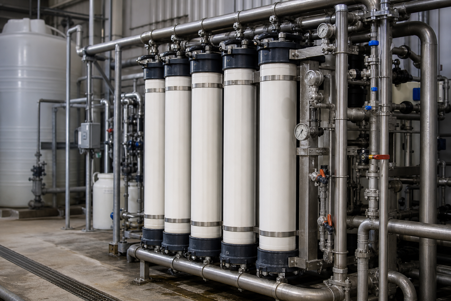
The process chain runs in four steps. First, the scrubber bleed receives one-shot chemical softening – alkali dosing that reacts hardness ions and reactive silica into filterable solids. Second, the reacted liquor passes through a tubular membrane (TMF) unit, which replaces the conventional sedimentation-and-filtration chain in a single solid-liquid separation step. The membrane permeate carries calcium, magnesium, barium, strontium and silica down to levels that protect the downstream evaporation surfaces; the concentrated softening sludge is bled off for dewatering.
Third, the TMF permeate enters the MVR evaporation island, designed in two thermally series blocks: a falling-film concentrator that does the bulk water removal at high heat-transfer coefficient, followed by a forced-circulation crystallizer that takes the concentrated brine through saturation to a dischargeable crystal slurry. Falling film is chosen for the front end because dilute-to-moderate brine wets tubes efficiently and the block handles the largest vapor load; forced circulation is chosen for the back end because high circulation velocity suppresses tube-wall supersaturation, scaling and plugging exactly where salt is being made.
Fourth, the crystal slurry reports to a thickener and then a centrifuge, which separates free liquor from the salt cake. Distillate from both evaporation blocks condenses clean and returns to the scrubber circuit as makeup, closing the water loop. The compressor recycles the secondary vapor as the heating medium, so the train runs on electrical power rather than continuous live steam – the defining OPEX lever of MVR in this duty.
Technical Features That Decide Whether the Loop Stays Closed
Three features carry most of the engineering weight in this application. The first is the softening-and-TMF front end. Silica and hardness that survive into the evaporator will deposit on heat-transfer surfaces within weeks; the TMF step exists to make that failure mode structurally unlikely rather than to be cleaned up after the fact. Keeping the membrane as the sole solid-liquid boundary also shortens the flowsheet compared with a clarifier-plus-filter chain, which the reference supplier highlights as a footprint and operability advantage.
The second is the split between falling-film concentration and forced-circulation crystallization. Trying to crystallize in the same body that concentrates wastes the falling film’s coefficient advantage; trying to run the whole train as falling film risks dry-out and scaling at the saturation end. The two-block split lets each section operate where its hydraulic regime is genuinely appropriate.
The third is the sidestream architecture itself. Because only the salt-bearing purge goes to ZLD, the evaporator is roughly an order of magnitude smaller than a full-flow design would be. This is the single most consequential economic decision in scrubber-loop ZLD, and it is made in the water balance, not in the equipment selection.
Process Modules
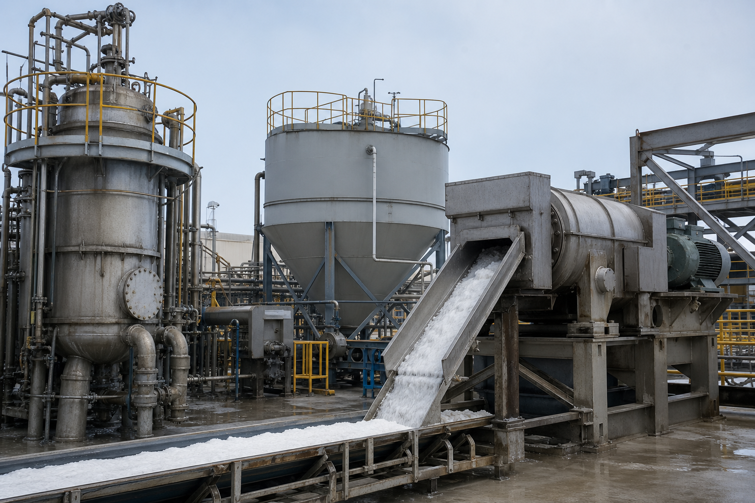
| Process module | Candidate equipment types | Selection rationale | Module duty |
|---|---|---|---|
| Softening reaction | One-shot chemical softening (alkali/soda ash dosing vessels) | Precipitates Ca/Mg/Ba/Sr and reactive silica ahead of membrane | Convert dissolved scale precursors to filterable solids |
| Solid-liquid separation | Tubular membrane filter (TMF) | Replaces clarifier + media filter; stable permeate quality at high solids | Deliver low-hardness, low-silica permeate to evaporation |
| Concentration block | MVR falling-film evaporator | High heat-transfer coefficient at dilute-to-moderate TDS; low specific volume | Bulk water removal from ~6% to near-saturation |
| Crystallization block | MVR forced-circulation crystallizer | High circulation velocity resists scaling and plugging at salt-making end | Produce dischargeable crystal slurry |
| Slurry dewatering | Thickener + centrifuge (or filter) | Thickener densifies slurry; centrifuge yields handleable cake | Separate salt solids from mother liquor |
| Vapor cycle | Centrifugal vapor compressor + surface condenser/polisher | Electrically driven heat pump over the boiling loop | Recompress secondary vapor as heating medium |
Configuration, materials and operating envelopes above are potential considerations only; actual selections depend on feed composition, temperature, corrosion review, fouling behavior, utilities and project capacity.
Expected Performance and Limits
Water recovery in this architecture is high by construction: essentially all evaporated water returns as condensate, so recovery is set by the salt and solids content of the purge rather than by the evaporator itself – typically above 90% of incoming volume for a 5-8% TDS feed (engineering estimate assuming complete salt retention in the cake). Specific energy for MVR concentration-crystallization duties of this kind generally falls in the 20-40 kWh per cubic meter of water evaporated range forchloride brines at this concentration (engineering estimate; actual value depends on ΔT design, compressor efficiency and condenser approach temperatures). Supplier-published material for the reference plant lists 35 t/h evaporation capacity for a 20 m³/h purge, with stable operation and simplified maintenance reported – supplier-published indicative range, not a project guarantee.
Limits worth respecting: the TMF front end removes scale precursors but not dissolved organics, so feeds carrying significant COD need an oxidation or carbon step somewhere in the train; and the salt cake from a mixed cation chloride brine is normally a disposal or valorization question that must be answered locally before the water balance can be declared closed.
Industry References and Validation
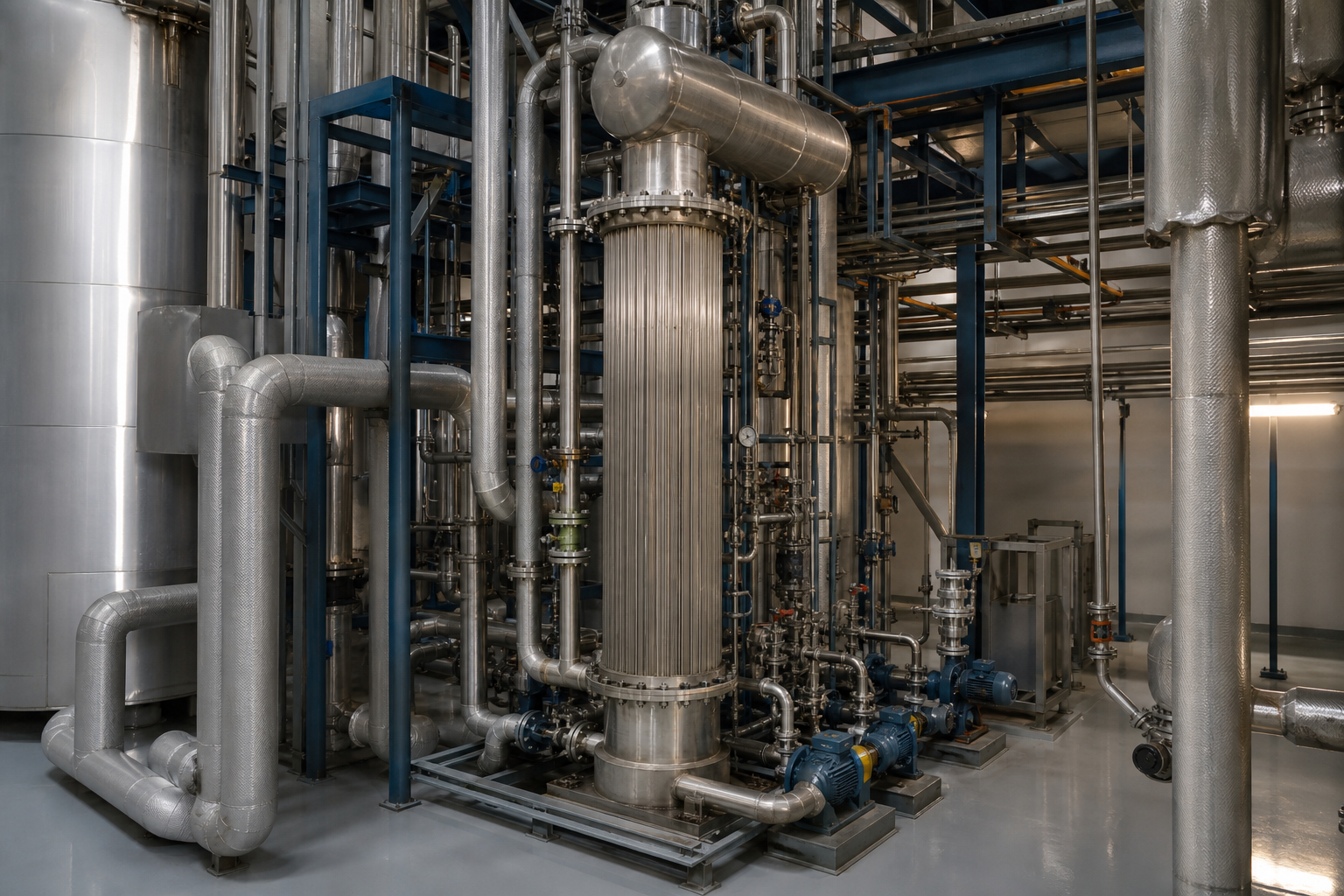
The configuration described here is anchored on a public supplier case: a supplier-published optical fiber plant flue gas scrubbing wastewater ZLD project, which reports a 35 t/h MVR double-section evaporator (falling-film concentration plus forced-circulation crystallization) behind chemical softening and tubular membrane filtration, treating a 20 m³/h purge from a ~6.9% TDS chloride scrubber liquor. This is an external industry reference, not an EvapCryst delivery; the reported outcomes are indicative, not a project guarantee. For your own project, validation effort should concentrate on three items: a full water and salt balance across the scrubber loop to fix the purge rate; a softening-and-TMF jar/membrane trial on actual scrubber water to confirm silica and hardness removal; and a boiling-point-rise and scaling tendency assessment of the concentrated brine to set the crystallizer operating window.
Frequently Asked Questions
Why not send all the scrubber water to the ZLD system?
Because the salt only accumulates at the purge rate. Treating the full circulation flow would multiply evaporator capacity – and cost – roughly tenfold for the same salt removal. The blend-and-purge architecture upstream is what makes ZLD affordable here.
Why use a tubular membrane instead of a clarifier and filter?
The TMF combines softening solids separation and permeate polishing in one unit with a sharp, stable cut. It protects the evaporator with permeate quality that a gravity clarifier cannot hold at variable solids load, and it does so in a smaller footprint with simpler operation.
Does the salt have resale value?
Usually not in this application. The brine is chloride-dominant but carries mixed cations and traces of process-specific species, so the cake is generally managed as a solid waste or valorized locally where a market exists. Salt quality requirements should be scoped before promising any outlet.
MVR or multi-effect for this duty?
MVR suits sites where steam is expensive or unavailable and electricity is reasonably priced; multi-effect suits sites with abundant low-cost steam. For scrubber ZLD the supplier reference explicitly selected MVR over MED for footprint and efficiency reasons at this scale.
What is the main scaling risk?
Silica, followed by hardness carbonates and sulfates. Both are addressed in the softening-TMF block, which is why that block – not the evaporator – deserves the early process development attention.
When This Route May Not Fit
This architecture assumes a chloride-dominant, low-organic purge. If your scrubber water carries heavy COD, solvents or surfactant loads, the evaporator will see foaming and volatile carryover, and a biological or oxidation step must be added – at some point a different water architecture becomes cheaper. If the plant has essentially free waste steam and electricity is expensive, multi-effect evaporation may beat MVR on operating cost. And if the purge flow is very small (a few cubic meters per day), trucking the brine off-site can remain the rational choice for longer than most teams expect.
What Must Be Verified Before Committing
Four items: a 24-hour profiled water balance and composition of the scrubber loop (TDS trend, silica, hardness, any organics); a softening plus TMF bench trial on real water, including membrane flux stability over several cycles; boiling-point-rise and crystallization behavior of the concentrated brine; and a disposal or valorization route for the salt cake under local regulations. These map directly onto the modules above and are the standard screening package we would run before any quote.