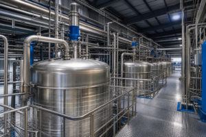
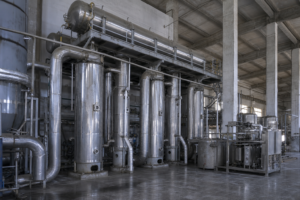
For coal chemical brines where sodium chloride and calcium chloride coexist, scaling control in the falling-film evaporator is not a cleaning-schedule question – it is a phase-equilibrium question. The workable design method, validated in the peer-reviewed literature, is to combine measured solid-liquid equilibrium data for the NaCl-CaCl2-H2O system with numerical simulation of the falling film, so that the tube length at which NaCl crystallizes out is predicted before the evaporator is built, and the unit is designed to keep that event inside a zone the hardware can tolerate. The design premise: in this mixed-salt system NaCl is the salt that falls out first and it does so at a calculable point – if your evaporation tube is still superheated past that point, you are growing scale on the wall deliberately.
Why Mixed NaCl-CaCl2 Brines Scale Where Pure Brines Do Not
Coal chemical high-salinity wastewater after membrane concentration carries Na+, Ca2+ and Cl- as its principal ions – the NaCl-CaCl2-H2O ternary family. The thermodynamic behavior of that system has a consequence that pure-salt intuition misses: as CaCl2 dissolves to high concentration, the common chloride ion shifts the dissolution equilibrium of NaCl and suppresses its solubility (the common-ion effect), while NaCl’s own solubility climbs only slowly with temperature. The result, established experimentally at 303.15-373.15 K, is that NaCl has the larger crystallization field of the pair – in this system NaCl crystallizes out first, readily, and at concentrations the designer must know in advance (Li et al., Water Supply 22(10) 7547, IWA Publishing 2022 – peer-reviewed source; mechanism may be cited as established).
In a vertical falling-film evaporator tube, the liquor film heats and concentrates as it descends. At some axial position the local NaCl concentration crosses the saturation surface; beyond that point the film is supersaturated and crystallization begins wherever there is a surface to grow on – including the tube wall. The engineering failure mode is not that crystallization happens, it is that it happens at an unexamined position with unmanaged wall supersaturation, producing a hard, insulating scale layer that degrades heat transfer and eventually blocks the tube.
The reference study is direct about the consequences of getting this right: for four coal-chemical saline waters (10% NaCl with 9, 10, 11 and 12% CaCl2), simulation built on the measured phase equilibria predicted NaCl crystal precipitation at tube lengths of 718, 942, 966 and 1,000 mm respectively in a 1,000 mm test tube – and a physical falling-film rig confirmed measurable positive fouling rates at exactly those predicted stations (Li et al., Water Supply 22(10):7547 – external peer-reviewed reference).
Illustrative Feed Envelope for Screening
The envelope below consolidates the published experimental matrix with ranges used for screening mixed NaCl/CaCl2 coal-chemical concentrates. It is an illustrative envelope built from published research data and stated assumptions – not a customer dataset, and not a performance guarantee.
| Parameter | Illustrative range | Basis / note |
|---|---|---|
| NaCl mass fraction | ~10% at evaporator inlet, rising through the tube | Published experimental matrix |
| CaCl2 mass fraction | 9-12% at inlet | Four-water test series |
| Wall / inlet temperature | 380 K wall class; 303 K inlet class | Published simulation boundary conditions |
| NaCl at crystallization onset | ~16% w/w at the crossing point | Measured solubility at film conditions |
| Predicted onset position | 718-1,000 mm of a 1,000 mm tube | Lower salt content crystallizes earlier |
| Treatment objective | Keep NaCl precipitation inside a controlled zone; recover both salts | Scaling-managed design |
Process Solution: Predict the Crossing Point, Then Design Around It

The method runs in four steps. First, characterize the phase equilibrium of the actual brine. For the reference ternary the measured data show a simple mesostable phase diagram with regular component variation between 303 and 373 K when NaCl sits at 15-28% – the co-saturation point shifts with temperature, and the CaCl2 hydrate that crystallizes on the calcium-rich side changes form (dihydrate through hexahydrate) as temperature falls. This data is the foundation; guessing it is how scale incidents happen.
Second, simulate the film. A volume-of-fluid (VOF) two-phase model of the tube, using the fitted physical properties of the brine (density, viscosity, heat capacity, conductivity as functions of temperature), reproduces the film’s heating and evaporation along the tube: rapid temperature rise at the inlet where film-wall ΔT is large, film temperature stabilizing around 370-377 K toward the outlet, and accelerating evaporation as the film thins. The simulation delivers the axial profile of w(NaCl) and w(CaCl2) – the concentration trajectory the liquor actually follows.
Third, overlay the two: where the simulated concentration trajectory crosses the measured solubility surface is the predicted crystallization onset. In the reference work the four test brines crossed at 718, 942, 966 and 1,000 mm – and notably, the leaner brines (lower total salt) crystallize earlier, because higher thermal conductivity speeds their heating and evaporation, concentrating them faster. Fourth, design against that knowledge: keep the highest wall superheat upstream of the crossing point, manage film velocity and wetting through the crystallization zone, extract the crystal-bearing liquor to a forced-circulation or suspension-crystallizer body before wall supersaturation accumulates, and set cleaning access where the physics says deposition will concentrate. The experimental rig in the reference verified the approach by measuring positive fouling rates at each predicted station – the method predicts where scale starts, which is exactly what a cleaning program and a slurry-handling design need to know.
Technical Features That Decide Whether the Tube Stays Clean
Three features carry the engineering weight. The first is honest equilibrium data for your actual brine. The published NaCl-CaCl2-H2O data covers a specific composition window; magnesium, sulfate or organics in real coal brines shift the surfaces. Bench solubility work on the real concentrate – not literature values alone – is the price of a defensible prediction.
The second is the film-side heat-flux profile. Because the film heats fastest at the inlet and evaporates fastest late in the tube, wall superheat and concentration growth are distributed unevenly along the length. A design that concentrates its ΔT where the liquor is still dilute and deliberately tapers it through the crystallization zone keeps the wall from being the preferred nucleation surface.
The third is where crystallization is allowed to finish. The falling-film tube is a concentrator; the salt-making should be handed off to a crystallizer body designed for slurry – forced circulation with high tube velocity, or a suspension design where crystals grow in the bulk. Asking the falling film to both concentrate and finish crystallization is the classic design error this method exists to prevent.
Process Modules

| Process module | Candidate equipment types | Selection rationale | Module duty |
|---|---|---|---|
| Brine characterization | Solid-liquid equilibrium measurement / solubility study | Real-brine saturation surfaces under design temperatures | Fix the crystallization boundary |
| Film prediction | Two-phase CFD (VOF class) with fitted brine properties | Axial concentration and temperature trajectories | Locate the NaCl crossing point |
| Concentration block | Falling-film evaporator with managed wall-flux profile | High coefficient while liquor is dilute; protected through crossing zone | Concentrate to near-saturation without wall deposits |
| Crystallization block | Forced-circulation crystallizer or suspension body | Bulk-phase crystal growth at high velocity | Finish crystallization off the wall |
| Materials | Potential material considerations: chloride-resistant grades through calcium-rich sections | CaCl2 fraction raises corrosion risk | Contain the brine through its full path |
| Monitoring and cleaning access | Fouling instrumentation; distributed cleaning ports | Deposition concentrates at predicted stations | Keep heat transfer recoverable |
Configuration, materials and operating envelopes above are potential considerations only; actual selections depend on feed composition, temperature, corrosion review, fouling behavior, utilities and project capacity.
Expected Performance and Limits
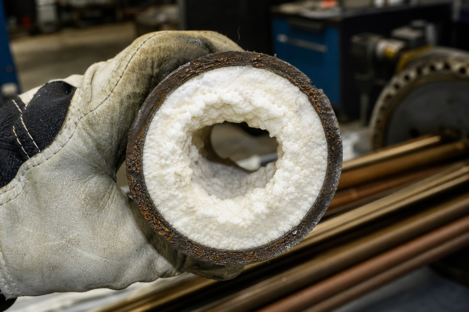
What this method buys is predictability rather than a single number: the reference study demonstrated that phase-equilibrium-plus-simulation can locate the crystallization onset within a falling-film tube with experimental confirmation at four compositions (Water Supply 22(10):7547 – external peer-reviewed reference; indicative of the method, not a project guarantee). Engineering estimates from the same data: at the crossing point the NaCl mass fraction sits around 16% for the reference family, the onset moves earlier as total salt content falls, and film outlet temperatures settle in the 370-377 K class under the reference wall condition. Limits worth respecting: the method is only as good as the equilibrium data behind it – trace components shift the surfaces; prediction locates the onset of crystallization but does not by itself suppress it, so the hardware decisions above still carry the protection; and the calcium-rich end of the system crystallizes as hydrated CaCl2 at lower temperature, which changes both the corrosion picture and the crystal-handling duty if the train runs cold.
Industry References and Validation
The route is anchored on the peer-reviewed study “Scaling trend of coal chemical saline wastewater in falling film evaporator: experimental solid-liquid equilibrium and numerical simulation” – Li, Liu, Liu, Jiang, Zhang, Gao and Xue, Water Supply 22(10) 7547-7564, IWA Publishing, September 2022, measuring the NaCl-CaCl2-H2O ternary at 303.15-373.15 K and predicting NaCl precipitation loci at 718-1,000 mm of tube length, verified on a falling-film test rig (an external peer-reviewed reference; mechanism and data may be cited, not claimed as EvapCryst work). Complementary process context comes from supplier-published coal-chemical ZLD practice, where membrane concentrate at 6-12% salt is routed to thermal evaporation-crystallization with freezing crystallization for salt separation (a supplier-published coal chemical ZLD overview – an external industry reference, not an EvapCryst delivery; supplier-published indicative process description). For your own project, validation effort should concentrate on: solubility measurement of your actual concentrate across your operating temperature window; a film simulation with fitted properties to locate your crossing point; corrosion assessment weighted to the CaCl2 fraction; and a rig or pilot fouling run long enough to see the deposition rate at the predicted station.
Frequently Asked Questions
Which salt scales first in a NaCl-CaCl2 brine?
NaCl. Its crystallization field in the ternary system is larger, and the common-ion effect of dissolved CaCl2 actively suppresses NaCl solubility – so as the film concentrates, NaCl reaches saturation first and is the deposit you must design against.
Why does a leaner brine crystallize earlier in the tube?
Lower salt content means higher thermal conductivity, so the film heats and evaporates faster – its concentration rises more steeply with tube length and crosses the saturation surface sooner. The counterintuitive result is that diluting the feed does not push scaling later; it pulls it earlier.
Can’t I just clean the tubes more often?
You can, but you are paying for chemistry with availability. Hard crystalline NaCl scale resists chemical cleaning and forces mechanical access, and every fouling interval costs heat-transfer coefficient and capacity. Locating and managing the crystallization zone is cheaper than fighting it after the fact.
Does this analysis matter for forced-circulation evaporators too?
Less critically – forced circulation exists precisely to keep tube velocity high and wall supersaturation low. But the same equilibrium data still sets the concentration ceiling and the crystallizer feed condition, so the characterization step transfers even when the evaporator type changes.
What about the CaCl2 itself?
It concentrates past the NaCl crossing and crystallizes later – as hydrated salts, and with a hydrate form that depends on temperature. It is also the corrosion driver in the train, so materials selection tracks the calcium-rich end of the process, not the average.
When This Route May Not Fit
If your brine is single-salt or dominated by one component with the other at trace level, the ternary crossing-point analysis simplifies to ordinary saturation management and the extra characterization effort is not justified. If organics, surfactants or suspended solids dominate the fouling picture, crystallization prediction is necessary but not sufficient – the deposit will be composite and the pretreatment question comes first. And if the plant’s throughput is small, a conservative forced-circulation-everywhere design may cost less than the engineering study that optimizes a falling-film train.
What Must Be Verified Before Committing
Five items: a solubility study of your actual concentrate across the operating temperature window; a film simulation with properties fitted to your brine, reporting the axial concentration trajectory; the predicted crossing point cross-checked against a physical fouling test at pilot scale; a corrosion review weighted to the calcium chloride fraction and its hydrate chemistry; and a crystallizer interface specification that takes delivery of the liquor at a defined supersaturation. These map directly onto the modules above and are the standard screening package we would run before any quote.