EvapCryst logo

Multiple-Effect Evaporation (MED) Systems

Vapor boiled off in one effect becomes the heating steam for the next, which operates at lower pressure and temperature. Live steam drives only the first effect — steam economy scales roughly with the number of effects, making MED the lowest-CapEx reuse route wherever low-pressure steam already exists on site.

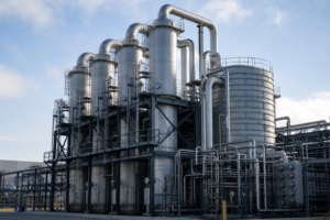
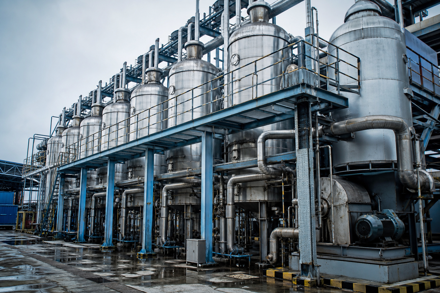
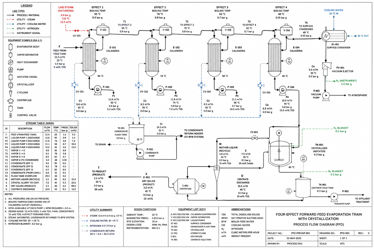
Multiple effect evaporation system with evaporators connected in series
At a Glance

Four Numbers That Define MED

Reference ranges under typical operating conditions — where your project lands inside each range depends on the variables in the effect-count economics table.

Specific Steam
0.25–0.40 t/t
tonnes of live steam per tonne of water evaporated — 3–5 effects typical
Single-Effect Baseline
~1.0 t/t
every kilogram of water evaporated consumes a kilogram of live steam — no vapor reuse
Live Steam Pressure
4–10 bar(g)
low-pressure header is sufficient — no compressor, no high-pressure motive steam
Cooling Water
25–32 °C
required at the final-effect surface condenser — the vacuum-creating element of the train
Working Principle

The Pressure Staircase

Live steam drives only the first effect. Each subsequent effect operates at lower pressure and temperature, so the vapor from the effect before it can still condense — one kilogram of live steam evaporates water again and again as it walks down the staircase.

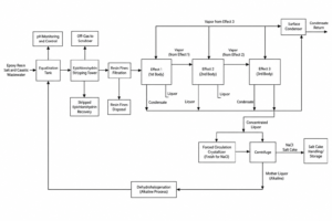
Simplified Multi-Effect Flow Diagram

Feed → Effect 1 (boil, highest T) → Effect 2 (lower T) → Effect 3 (lowest T) → Surface condenser → Distillate

Each effect runs at a lower pressure than the one before it — the temperature difference between consecutive effects only needs to cover the boiling-point elevation plus the driving ΔT across the heat-transfer surface.

01

Live Steam to Effect 1

Low-pressure steam at 4–10 bar(g) boils the feed in the first effect and returns as condensate — the only live-steam input to the train.

02

The Pressure Staircase

Each subsequent effect operates at lower pressure and temperature, so the vapor from the effect above it condenses progressively lower down the train — yet still holds a usable ΔT.

03

Cascade Reuse

The same kilogram of steam evaporates water in effect after effect. Steam economy approaches the number of effects — but never reaches it, because BPE and losses accumulate.

04

Final-Effect Condensation

Vapor from the last effect condenses against 25–32 °C cooling water. The condenser creates the vacuum that pulls the whole pressure staircase down.

Effect-Count Economics

Why 3–5 Effects, Not 10

Steam economy scales with effect count — but so does CapEx, footprint and cooling load. The table shows where the economics stop paying.

Effect CountSpecific SteamTypical DeploymentWhy Stop There
Single-effect1 EFFECT
~1.0 t steam / t waterno vapor reuse — the baselineSmall plants, batch service, throttle duty where steam is a by-productEvery kilogram of water evaporated consumes a kilogram of live steam
2–3 effectsWORKHORSE
0.40 t steam / t watertypical at 3 effectsMedium-scale process concentratorsBest balance of CapEx and steam economy on most utility price structures
4–5 effectsLARGE SCALE
0.25 t steam / t watertypical at 5 effectsLarge-scale food, pulp and coal-chemical concentratorsRequires plot area and cooling-water capacity for the final-effect condenser
Beyond 5–6RARELY ECONOMICAL
Diminishing returnseconomy approaches N, never reaches itOnly where steam is extremely expensive and plot area is freeMarginal CapEx of an additional effect exceeds the marginal steam savings

Steam economy (tonnes of water evaporated per tonne of live steam) approaches N for an N-effect train but never reaches it — boiling-point elevation consumes effective ΔT at each effect, heat losses accumulate, and the last effect carries the full cooling-water load. Figures reflect typical industrial ranges observed in operating references; project-specific selection requires heat and mass balance, utility cost modeling (steam vs. electricity) and site steam-header capacity analysis.

Feed Arrangements

Forward, Backward or Mixed Feed

Within any effect count, three feed arrangements are possible. The choice is set by feed temperature, viscosity profile and product concentration — decided from the heat and mass balance, not from a catalog.

01 · Forward Feed

Feed Enters Effect 1

Liquor flows in the same direction as the vapor — down the pressure staircase. Gravity and pressure gradient carry the feed, no intermediate transfer pumps; the default for hot, low-viscosity feeds close to boiling.

4–10 bar(g)live steam to Effect 1 — the only external heat input
02 · Backward Feed

Feed Enters the Last Effect

Cold feed recovers heat from the warmest effect last — transfer pumps step the liquor up the staircase. Suits cold feeds and concentration duties where viscosity rises with concentration.

2–5 effectsCapEx scales roughly linearly with effect count — the economics table governs where to stop
03 · Mixed Feed

Feed Enters an Intermediate Effect

The feed splits across the train at an intermediate point, part forward and part backward. Selected case by case when the heat and mass balance shows a heat-recovery or viscosity advantage no pure arrangement delivers.

Case-by-casejustified only by the project heat and mass balance, never selected from a catalog
Hybrid Routes

When One Strategy Isn't Enough

MVR, multi-effect and TVR are not mutually exclusive. Hybrids are common when a single strategy cannot meet the energy target within CAPEX constraints.

Documented Hybrid Configurations

MED combined with — not opposed to — compression routes

Two hybrid patterns lift steam economy or cut live-steam demand without abandoning the train:

(a) TVR booster on Effect 1 — motive steam at ≥8 bar(g) entrains and recompresses process vapor
(b) MVR retrofit on Effect 1 — electrifies the first effect of an existing multi-effect train

Both patterns keep the downstream effects exactly as they are. See the Retrofit & Decarbonization solution line for where each pattern is standard practice. High-BPE feeds where MVR alone would push past the compressor envelope also screen better as MVR + multi-effect hybrids.

Technical Specifications

Multi-Effect System Envelope — Published Supplier Data

Indicative ranges aggregated from published supplier specifications of multi-effect evaporator builders (standard, food-grade and salt-line executions). For route screening only — not a process guarantee for any specific project.

System SectionParameterPublished Indicative RangeApplies To / Basis
Whole trainCapacity range0.08–900 t/h published family span · standard series 3,000–50,000 kg/hpilot-scale to full plant fleets; the 0.5–80 t/h family covers most industrial duties
Steam economyPer effect / system0.7–0.9 kg vapor per kg first-effect steam, per effect · system SE 2.0–7.02–7 effect trains; TVR or MVR add-ons lift SE further
Steam consumptionEffect-count gradient1E 1.1–1.2 · 2E 0.6–0.7 · 3E 0.37–0.46 · 4E 0.30–0.35 · 5E 0.24–0.30 t steam / t waterthe defining trade: each added effect cuts steam but adds surface and capital
Effect countPractical window2–7 effects practical (3–5 most common) · 8 published maximumlimited by total ΔT and boiling point elevation of the feed
First effectLive steam0.6–1.0 MPa(abs) saturatedsite steam supply class; LV steam duties take a TVR instead
Temperature staircaseEffect-by-effect profile3E 99/76/53 °C @ 0/448/640 mmHg · 4E salt 106/90/70/47 °C · food 75/62/50 °Clast effect runs 45–65 °C under vacuum
UtilitiesAuxiliary electricity / cooling water8–15 kWh per t evaporated · cooling water 8–28 t per t (1E/2E/3E with thermocompressor)pumps, vacuum and controls; 20 °C in / 40 °C out cooling basis
TVR add-onThermocompression−33% steam vs plain double-effect (≈ +1 effect equivalent)requires ≥0.6 MPa live steam; ejects ≈0.3 kg secondary vapor per kg HP steam
MaterialsWetted partsSS304/SS316L · duplex 2205/2507 · Tiduty-side chemistry selection
FootprintPublished skid dimensions3E 200–500 LPH: 4×2.5×4.5 m · 1,000 LPH: 5.5×3×5.5 m · 2,000 LPH: 7×3.5×6.5 mpackaged executions
ServiceMaintenance basistube life 8–12 years · monthly CIP publishedfouling wastewater duties; automatic in-line cleaning on clean feeds

Ranges aggregate published specifications from multi-effect evaporator builders (chemical, food, pharma and vacuum-salt executions). Figures are supplier-published indicative values for screening; a project number requires heat and mass balance on your feed, effect-count economics against steam and electricity prices, and site utility data.

Main Process Modules

The Train, Module by Module

Each module is selected on feed chemistry and duty — the envelope column gives published operating ranges per module type, not a single-project specification.

ModuleEquipment TypesSelection BasisIndicative Operating Envelope
Effect bodies (calandrias)Falling-film · forced-circulation · natural-circulation tubular · pillow-platefeed viscosity, fouling and crystallization set the body type per effectstaircase 106→47 °C (salt) or 99→53 °C (standard 3-effect)
Thermocompressor (TVR)Steam-jet ejector on the first effectsite steam ≥0.6 MPa available and steam price justifies it≈+1 effect equivalent; −33% steam vs plain 2-effect
Feed preheatersCondensate / vapor-bleed heat-recovery trainsheat integration ahead of the first effectcondensate and secondary-vapor heat recovery published as standard
Final condenser & vacuumSurface / direct-contact condenser + vacuum pump or ejectorlast-effect vacuum level and NCG removal640 mmHg-class vacuum on the final effect
Salt separationDTB / cooling crystallizer + centrifugewhen a saleable salt is the product of the trainNaCl ≥98.5% published for the vacuum-salt line
CIPIn-line cleaning with automatic sequencefouling wastewater dutiesmonthly CIP; tube life 8–12 years published
ControlsPLC/HMI recipe + density-triggered dischargeTDS endpoint control across the trainon-line density / conductivity trip to discharge or recirculation

Module envelopes follow the published supplier data above; effect count, feed direction (forward / backward / mixed) and ΔT split are project-specific and set at design.

Multi-Effect in the Field — Case Studies & Technical Guides

Limitations to Design Around

Larger footprint (×N bodies), higher absolute steam demand at part-load, and last-effect cooling-water consumption are the standing constraints. Steam economy never equals the effect count — boiling-point elevation consumes effective ΔT at each effect. Screen against your site’s steam header capacity and cooling-water temperature, not catalog figures. All figures on this page are indicative ranges for preliminary screening, not a process guarantee.

FAQ · Engineering Answers

Multi-Effect Questions We Answer Most

Recurring questions from engineers screening a multi-effect route for the first time.

QShouldn’t more effects always be better? Why does the range stop at 5–6?

Steam economy approaches the number of effects but never reaches it — boiling-point elevation consumes effective ΔT at each effect and heat losses accumulate. Beyond 5–6 effects the marginal CapEx of an additional body exceeds the marginal steam savings. Three effects (about 0.40 t/t) is the workhorse for medium scale; five effects (about 0.25 t/t) is typical for large food, pulp and coal-chemical concentrators.

QThe range says 0.25–0.40 t steam per tonne of water. What decides my number?

Effect count first: 0.40 t/t is typical at three effects, 0.25 t/t at five. Then the decrement variables: feed boiling-point elevation, which consumes effective ΔT at every effect; heat losses across bodies and piping; and the final-effect condenser design basis, which is set by your 25–32 °C cooling-water temperature.

QWhat utilities does a multi-effect plant need on site?

A stable low-pressure steam header at 4–10 bar(g), sized for 0.25–0.40 tonnes of steam per tonne of water evaporated, plus cooling water at 25–32 °C for the final-effect surface condenser. No compressor and no large electrical duty — which is exactly why MED wins where steam is already on site and grid capacity is not.

QHow do I choose between forward and backward feed?

Forward feed needs no intermediate transfer pumps — gravity and the pressure gradient carry the liquor down the staircase — and suits hot, low-viscosity feeds close to boiling. Backward feed recovers heat from a cold feed and handles viscosity that rises with concentration, at the cost of transfer pumps stepping the liquor up the train. Mixed feed is justified case by case from the heat and mass balance.

QWhen is MED the wrong choice?

When there is no reliable low-pressure steam header on site, when electricity is cheaper than steam and the grid can support a compressor — then MVR at 15–25 kWh per tonne usually screens better — or when plot area and cooling-water capacity cannot host an N-body train with a surface condenser. The comparison page carries the full decision table.

Screening a Multi-Effect Route?

Send us feed analysis, throughput, site steam pressure and cooling-water temperature. We will return a preliminary MVR vs. multi-effect vs. TVR screening with indicative steam economy — not a brochure.

Request a Proposal

Send your feed characterization (TDS, COD, main salts, viscosity), throughput and product targets — we respond with a preliminary process route within two business days.