Polysilicon wastewater is a calcium-chloride problem: the modified Siemens process scrubs chlorosilane-laden tail gases with lime solutions, leaving high-salt, chloride-rich streams that no membrane alone can close. The proven zero liquid discharge route is a train — softening and pretreatment, membrane concentration, then mechanical vapor recompression evaporation feeding a crystallizer — that recovers process water and discharges calcium chloride as a tetrahydrate crystal byproduct. The approach is operating at industrial scale, per an external industry reference: a 25,000-ton-per-year high-purity crystalline silicon plant commissioned China’s first polysilicon-industry wastewater zero-discharge facility in 2022, and within its first months it had produced more than 150 tons of calcium chloride tetrahydrate as a saleable product (vendor-published project report, not an EvapCryst delivery; indicative, not a project guarantee).
Where Polysilicon Wastewater Comes From
High-purity polysilicon is made almost exclusively by the modified Siemens route: trichlorosilane is synthesized from metallurgical-grade silicon, purified by distillation, and deposited on heated rods inside reduction reactors. Chlorine circulates through the plant in a closed loop — hydrogen chloride, trichlorosilane, silicon tetrachloride, and dichlorosilane all appear as intermediates — but every loop leaks chemistry into the water system at predictable points. Tail-gas scrubbers absorbing chlorosilanes generate hydrochloric acid streams that are neutralized with lime, converting the load into calcium chloride. Cold hydrogenation, off-gas treatment, exhaust scrubbing, and equipment washdowns add streams with the same signature: high chloride, high calcium, low organics, and traces of silicic acid that polymerize into colloidal silica.
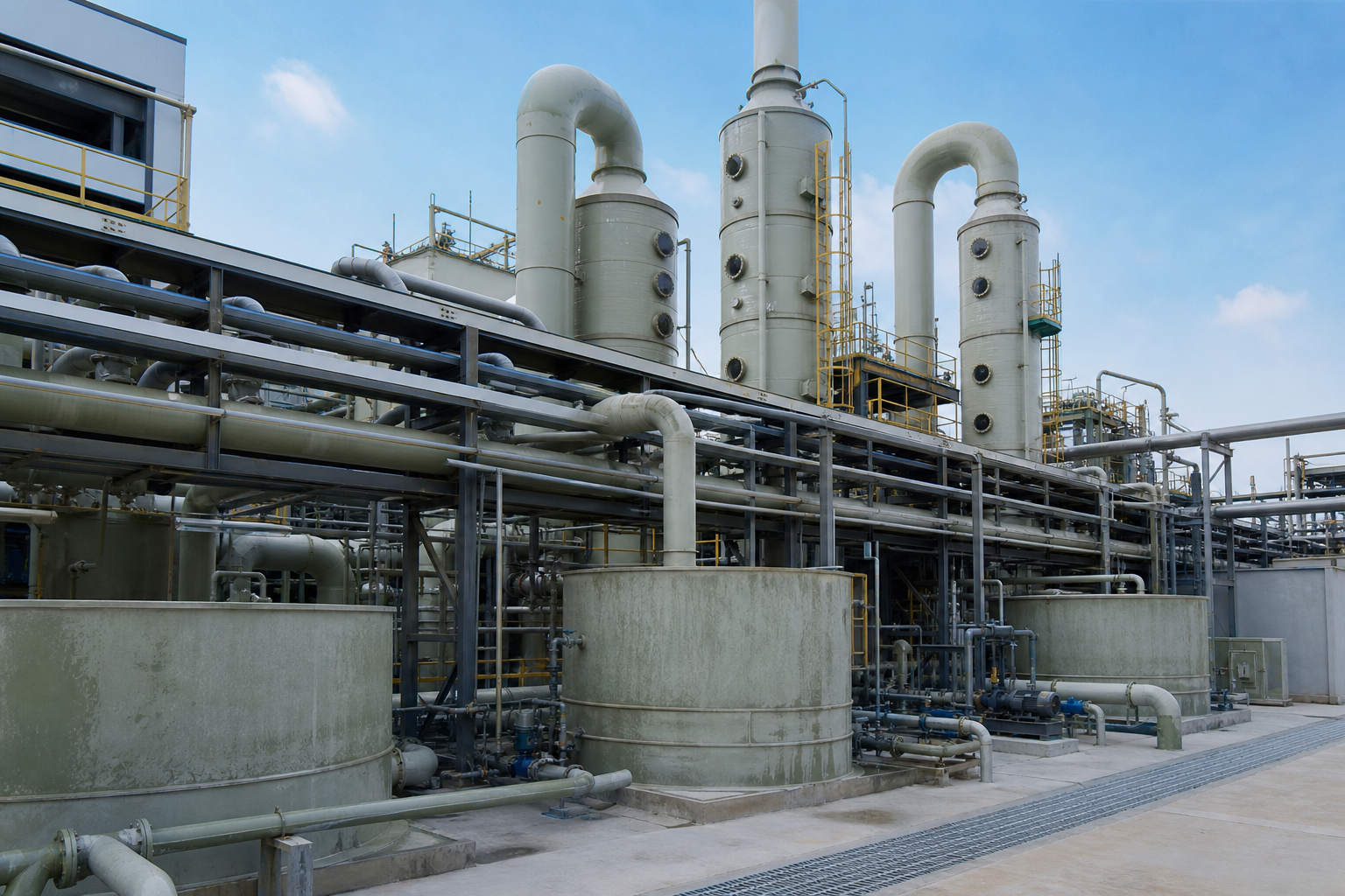
The result is a wastewater whose defining feature is not any single toxic component but sheer salt load combined with corrosive chemistry. Total dissolved solids in these streams are industry-reported to commonly run from several tens of grams per liter upward, dominated by CaCl2 with lesser NaCl, and the silica that escapes incomplete pretreatment is the most common cause of downstream fouling. Downstream of polysilicon production itself, PV manufacturing adds its own streams: diamond-wire sawing waste carrying polyethylene glycol and silicon particles, and cell-production etching baths of hydrofluoric and nitric acid. These are different problems from the polysilicon salt loop and need different unit operations, but they increasingly fall under the same zero-discharge permit umbrella.
Why Calcium Chloride Streams Are Difficult
Calcium chloride is one of the most demanding salts to evaporate, for reasons rooted in its physical chemistry. Its published solubility at 20 °C is roughly 745 grams per liter — an order of magnitude beyond common salts like sodium chloride — which means the water must be driven off to extreme concentration before any crystal appears, and the endpoint shifts with temperature in unhelpful ways. Concentrated CaCl2 solutions also exhibit a substantial boiling point rise; at high concentration this elevation reaches tens of degrees, which silently consumes the temperature difference that drives heat transfer and erodes the effective duty of an MVR compressor selected on water-alone assumptions.
Corrosion and viscosity compound the difficulty. Hot concentrated chloride brines attack standard austenitic stainless steels through pitting and chloride stress corrosion cracking, pushing material selection toward duplex stainless steels, higher-alloy grades, or titanium on wetted paths. High viscosity at concentration slows circulation in falling-film designs and encourages local over-concentration, which is why forced-circulation and scraper-type evaporators, tolerant of viscous slurry duty, are preferred for the back end of the train. None of these are exotic problems — they are the routine engineering content of a CaCl2 evaporation project — but a supplier who has not run chloride service before will rediscover them at your expense.
The Zero-Discharge Train
A polysilicon wastewater ZLD facility is assembled from the same blocks as other high-salt ZLD projects, tuned for calcium chemistry. Silica and hardness management come first, because both scale heat-transfer surfaces; then membranes make the cheap cut of volume; then thermal evaporation carries the stream to crystallization. The blocks and their outputs:
| Module | Candidate Equipment Types | Selection Rationale | Indicative Operating Envelope |
|---|---|---|---|
| Pretreatment | Lime/soda softening, coagulation, filtration | Precipitates silica and hardness that scale downstream surfaces | Stable, pH-adjusted feed for membranes |
| Volume reduction | RO, high-pressure RO, DTRO | Cheapest first cut of the salt-load volume | Permeate for reuse plus concentrate to thermal |
| Evaporation | MVR or multi-effect forced-circulation evaporator | Thermal concentration to near saturation; BPE-aware compressor sizing | Distillate plus concentrated CaCl2 liquor |
| Crystallization | Cooling or flash crystallizer | Freezes CaCl2·4H2O from concentrated liquor | Crystal slurry plus mother-liquor recycle |
| Solid handling | Centrifuge, dryer, packing | Protects hydrate state and byproduct grade | Bagged tetrahydrate within moisture limits |
Configuration, materials, and operating ranges depend on the actual feed, water chemistry, corrosion review, fouling behavior, site utilities, and project capacity.
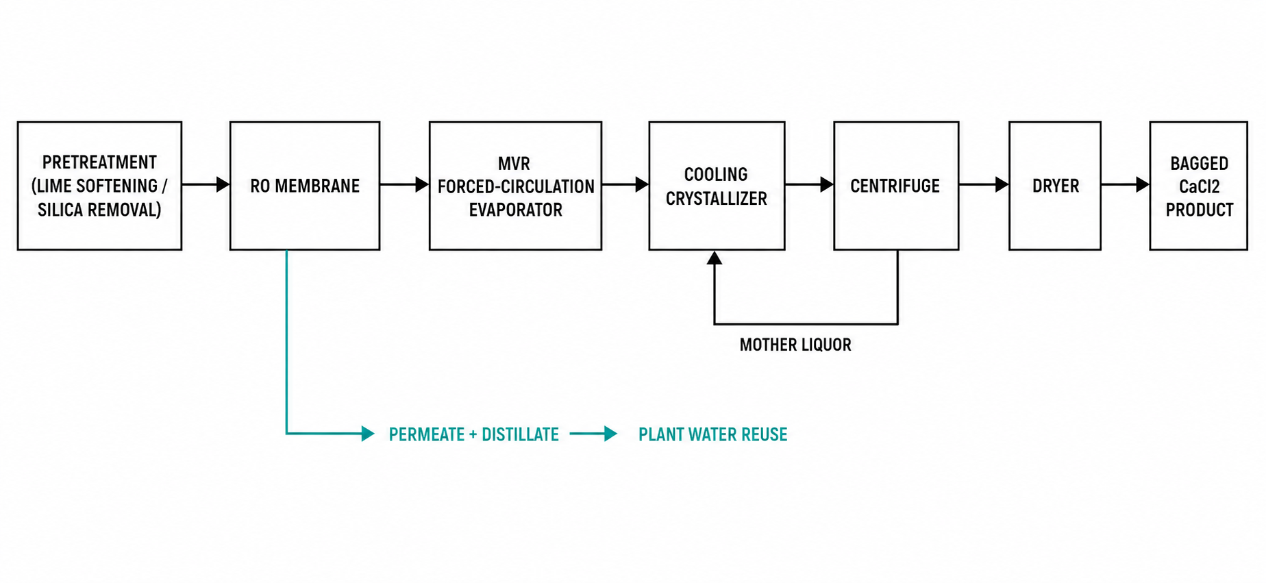
Two design choices deserve early attention. First, the evaporator type: MVR economizes on energy but its compressor must be specified against the boiling point rise of concentrated CaCl2, whereas multi-effect evaporation trades energy for simplicity and suits sites with process steam available — polysilicon plants usually have both electricity and steam, so the selection is genuinely site-specific. Second, the crystallizer endpoint: calcium chloride tetrahydrate freezes out of concentrated liquor on cooling, so the crystallizer, not the evaporator, often sets the byproduct quality.
A Benchmark: 25,000 Tons per Year of Crystalline Silicon
The external industry reference for this route is the wastewater concentration facility supplied for Tongwei’s 25,000-ton-per-year high-purity crystalline silicon plant, commissioned in September 2022 and reported by its supplier as the first zero-discharge wastewater project in China’s polysilicon industry (a third-party delivery, not an EvapCryst project). The facility concentrates the plant’s high-salt wastewater and crystallizes calcium chloride tetrahydrate — more than 150 tons produced in its initial operating period — turning a chronic wastewater liability into a product stream. For plant owners evaluating ZLD proposals, the case demonstrates three things at once: the technology is proven at full plant scale, the calcium chloride byproduct has a real outlet, and the project structure (an EPC-built concentration facility integrated with the silicon plant) is repeatable. Figures are vendor-published and indicative, not a project guarantee.
The Byproduct: Calcium Chloride Tetrahydrate
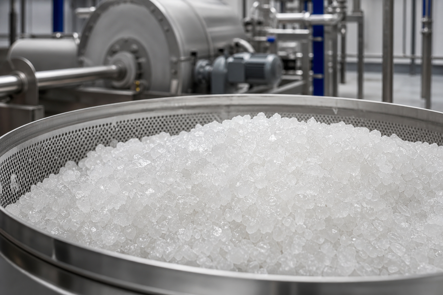
Zero liquid discharge only pencils out when the solid endpoint has somewhere to go, and this is where CaCl2 streams have an advantage over mixed salts. Calcium chloride tetrahydrate is a commodity with established demand — road deicing and dust control in cold climates, desiccant production, concrete acceleration, and industrial processing. A crystalline, baggable, consistently hydrated product meets those markets; a sloppy mixed sludge does not. Hydrate control matters commercially: CaCl2 forms several hydrates depending on temperature and concentration, and the tetrahydrate window must be held through crystallization, dewatering, and storage, since exposure of the product to dry air causes hydration-state drift and caking. These are ordinary product-quality disciplines, but they belong in the design basis, because byproduct revenue is what converts the ZLD line item from pure cost to partial offset.
PV Wafer and Cell Streams: A Different Animal
Upstream polysilicon salt loops get the most attention, but a full PV manufacturing site carries other wastewater fractions that often ride the same discharge permit. Diamond-wire sawing generates spent cutting fluid — polyethylene glycol-based, loaded with fine silicon particles — which is handled by filtration and centrifugation with PEG recovery or evaporation of the spent fluid. Cell production contributes acid etching wastes containing fluoride from HF-based texturing, which require fluoride precipitation as calcium fluoride before any salts are recovered. The practical consequence for site-wide water balance: these organic-bearing and fluoride-bearing fractions should be segregated at source rather than merged into the CaCl2 train, because PEG fouls evaporators and calcium fluoride is a classic reverse-soluble scale former that will find every hot surface. A well-run PV site therefore operates several small treatment trains with different chemistry, and a membrane-plus-evaporation backbone handling the salt.
Selection and Project Delivery Notes
When comparing suppliers for a polysilicon or PV wastewater project, three capabilities separate experienced vendors from the rest. Ask for chloride-service references with named alloys and operating hours — hot CaCl2 is unforgiving of material shortcuts. Ask how the boiling point rise is handled in the evaporator thermal design, because an MVR unit selected without it will underperform from day one at high concentration. And ask for the byproduct quality specification: moisture, hydrate state, and impurity ceilings that the crystallizer and dryer are contracted to deliver, since that specification is what the offtake market sees. Delivery models vary — integrated EPC contracting for the concentration facility, as in the externally referenced 25,000-ton benchmark, suits greenfield plants, while skid-mounted evaporator and crystallizer units suit capacity upgrades where plot space and tie-in time are constrained.
When This Route May Not Fit
The CaCl2-to-tetrahydrate route assumes the salt chemistry actually is calcium-dominated. Streams dominated by sodium chloride or mixed sulfate-chloride matrices do not freeze a clean tetrahydrate and belong on a different crystallization endpoint. Sites without a byproduct outlet, meaning no deicing, dust-control, or desiccant market within hauling distance, should compare against deep-well or secured liquid disposal before committing capital to crystallization. Low-salt streams of a few grams per liter are membrane problems and waste thermal capacity if evaporated. Fluoride- or PEG-bearing PV fractions must stay segregated: merging them into the calcium train buys fouling, not scale. MVR also loses its edge where cheap process steam already exists on site; multi-effect evaporation then delivers the same endpoint with less mechanical risk.
What Must Be Verified
Polysilicon ZLD scope must be verified before equipment is fixed. The wastewater characterization comes first: full ionic profile (Ca, Na, Cl, sulfate), silica level and its polymerization state, organics, and seasonal variation across the silicon plant’s operating modes. Silica and hardness behavior should be confirmed by pretreatment jar tests, because they set membrane and evaporator fouling risk. The boiling point rise of the actual liquor at target concentration drives evaporator and compressor sizing and must be measured, not assumed. Materials selection needs a chloride corrosion review at operating temperature. The byproduct specification of hydrate state, moisture, and impurity ceilings should be agreed with an offtake buyer in writing before the crystallizer is ordered. Each check prices a risk.
FAQ
What is the main salt in polysilicon wastewater?
Calcium chloride. Chlorosilane tail gases are scrubbed and neutralized with lime, converting chlorine to CaCl2, so the dominant dissolved load is a hot, corrosive, highly soluble calcium chloride brine with lesser sodium chloride and colloidal silica.
Why can’t RO alone achieve zero discharge at a polysilicon plant?
Membranes stall at high TDS due to osmotic pressure and silica scaling limits, and CaCl2’s extreme solubility means saturation is far away. Thermal evaporation and crystallization are required to reach a dry solid endpoint, with membranes used only for the first volume cut.
Is calcium chloride from wastewater actually saleable?
Yes, when crystallized as a consistent tetrahydrate product with defined moisture and impurity limits. Markets include road deicing, dust control, desiccants, and concrete acceleration. The externally referenced 25,000-ton-per-year Tongwei project (vendor-published, not an EvapCryst delivery) produced over 150 tons of the byproduct in its early operation.
MVR or multi-effect evaporation for CaCl2 service?
MVR saves energy but must be designed against the boiling point rise of concentrated CaCl2, which can reach tens of degrees and consumes compressor temperature lift. Multi-effect suits sites with available process steam and lowers mechanical complexity. Polysilicon plants frequently have both utilities, so the choice follows steam-electricity economics.
What materials survive hot concentrated calcium chloride?
Standard 316L is marginal in hot concentrated chloride: pitting and stress corrosion cracking drive selection toward duplex stainless steels, higher alloys, or titanium on wetted surfaces, with careful attention to gasketed joints and under-insulation chloride attack.
For a first-pass screening of a polysilicon or PV wastewater project, send the water analysis, salt load, and discharge target; in return you receive an indicative train architecture with evaporator type and byproduct direction, before any detailed engineering.