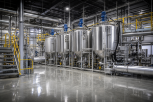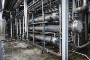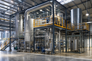
Fluoride wastewater cannot be biologically degraded, and chemical precipitation with lime runs into a hard physicochemical ceiling: calcium fluoride’s own solubility equilibrium leaves residual fluoride in the treated water, while the CaF₂ sludge it generates is itself a hazardous waste that must be hauled off-site. The industrially proven way out is evaporation and crystallization — concentrate the fluorine-bearing liquor thermally, crystallize the fluorine into a recoverable solid product, and return clean condensate to the process. In published new-energy references – an external industry reference, vendor-reported and indicative rather than a project guarantee – this approach is reported to cut hazardous waste volume by about 90% while achieving zero liquid discharge of the waste acid stream; this page explains where fluoride wastewater comes from, why precipitation stalls, and how the evaporation-crystallization route is configured.
Where Fluoride-Bearing Wastewater Comes From
Fluoride enters wastewater through a limited number of well-defined industrial channels, and identifying which one you are in determines the whole flowsheet. In the new-energy sector, lithium-hexafluorophosphate (LiPF₆) electrolyte chemistry and fluorinated binder production generate fluorine-bearing waste gas scrubbed by water or alkali, producing a dilute hydrofluoric/silicofluoric absorption liquor. Photovoltaic and semiconductor manufacturing use HF for wafer etching and texturing, discharging spent acid and rinse water. Phosphate fertilizer production liberates fluosilicic acid streams with the phosphogypsum; aluminum smelting contributes fluoride in pot scrubber water; and glass etching, metal surface treatment, and fluoropolymer production all add their own acid fluoride rinses.
The common denominator is that the fluorine arrives already dissolved, in acidic water, usually accompanied by sulfates, chlorides, or heavy metals from the host process. That combination is what defeats conventional treatment: the fluoride needs a thermal or chemical phase change to leave the water, and the accompanying matrix decides which one is affordable.
| Source industry | Typical fluorine form | Companion species | Preferred recovery route |
|---|---|---|---|
| Lithium battery / electrolyte materials | HF, fluorides from LiPF₆ decomposition | Sulfates, organics, lithium salts | Absorption → evaporation → crystallization; Li recovery ahead of F |
| PV / semiconductor etching | Spent HF, H₂SiF₆ | Acid, dissolved silica | Concentration → fluosilicate crystallization |
| Phosphate fertilizer | H₂SiF₆ in scrubber acid | Phosphates, sulfates | Evaporation → sodium/potassium fluosilicate product |
| Aluminum smelting | Fluoride in pot-gas scrubber water | Alumina, chlorides | Concentration → cryolite-path recovery |
Why Conventional Precipitation Hits a Wall
The default treatment — dosing lime or calcium chloride to precipitate CaF₂ — works down to a point and then stops, for a reason buried in the solubility product. CaF₂ is only sparingly soluble, but sparingly is not completely: once the water is saturated with the equilibrium concentration of calcium and fluoride ions, further dosing produces sludge without lowering the dissolved fluoride any further. Plants that must meet strict discharge limits therefore stack secondary steps on top — coagulation with aluminum salts, adsorption on activated alumina, or reverse osmosis — each adding cost and each generating its own waste stream.
The second, less discussed problem is the fate of the sludge. CaF₂ sludge loaded with heavy metals and trace organics is classified as hazardous waste in most jurisdictions, so every ton of fluoride removed by precipitation becomes a ton of paid disposal. Precipitation moves the problem from the water phase to the solid phase and sends the invoice to the waste-management budget line. This is the economic logic that pushes fluoride generators toward thermal treatment: if the fluorine must end up in a solid anyway, it is better to end up as a sellable fluoride chemical than as landfill.
The Evaporation–Crystallization Route for Fluoride Liquors
Thermal treatment of fluoride wastewater follows the same architecture as high-salinity ZLD — concentration, crystallization, solid–liquid separation, condensate return — but every equipment choice is filtered through fluorine chemistry. In the absorption-liquor case typical of new-energy plants, waste gas is first scrubbed in packed columns, and the resulting dilute acid liquor is fed to a multiple-effect or MVR evaporator. Water leaves as condensate clean enough for reuse in the scrubber itself; the fluorine concentrates until the liquor reaches crystallization conditions, and controlled cooling or evaporation precipitates a fluoride or fluosilicate salt that is separated, dried, and sold.
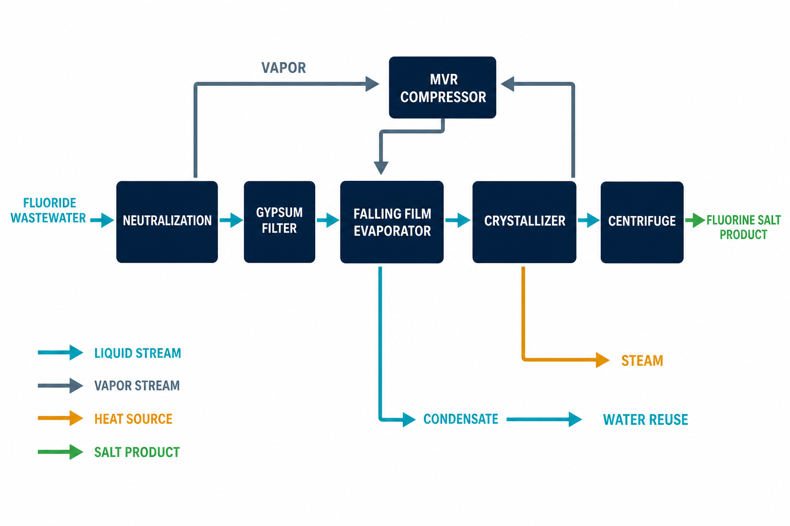
Published project experience from a new-energy fluorine recycling installation – cited as an external industry reference, supplier-reported and indicative, not a project guarantee and not a statement of EvapCryst delivery experience – shows what the endpoint looks like: fluorine recovered from waste-gas absorption liquor as a resource, hazardous waste volume reduced by roughly 90%, and zero liquid discharge of the waste liquid stream. Across Chinese industrial parks, tightening fluoride discharge limits are pushing evaporation-crystallization from a niche option into mainstream consideration as a zero-discharge route for fluoride wastewater. For the underlying thermodynamics of vapor recompression concentration, see MVR evaporation; for crystallizer architecture, forced-circulation evaporation and salt separation.
The route decomposes into standard process modules:
| Process module | Equipment candidates | Selection basis | Indicative envelope |
|---|---|---|---|
| Absorption | Packed scrubbing columns | Gas-side coordination sets liquor strength | Per gas load |
| Evaporation & concentration | Multiple-effect or MVR; graphite heat exchangers | HF-immune materials; energy economics | Per liquor survey |
| Crystallization | Controlled cooling or evaporative crystallizer | Target fluoride/fluosilicate salt | Per cation matrix |
| Solid-liquid separation & drying | Centrifuge; dryer | Product moisture and handling | Per crystal rate |
| Condensate return | Scrubber and process reuse routing | Closed water balance | Per site balance |
Configuration, materials, and operating ranges for each module depend on the actual feed, temperature, pressure, corrosion review, fouling behavior, utilities, and project capacity.
Materials Engineering: The Fluoride-Specific Constraint
Materials of construction are where fluoride projects are won or lost, and the selection is the mirror image of chloride brine practice. In chloride service — as covered in high-salinity wastewater systems — titanium and 2205 duplex stainless are the standard answers. Hydrofluoric acid attacks both. Even dilute HF corrodes stainless steels and titanium at useful rates, so wetted parts in fluoride service are specified in PTFE-lined steel, PVDF, graphite heat exchangers, and high-nickel alloys where the matrix allows; glass-lined reactors serve the more acidic duties. A supplier quoting standard 316L for an HF-bearing liquor is quoting a plant that will leak.
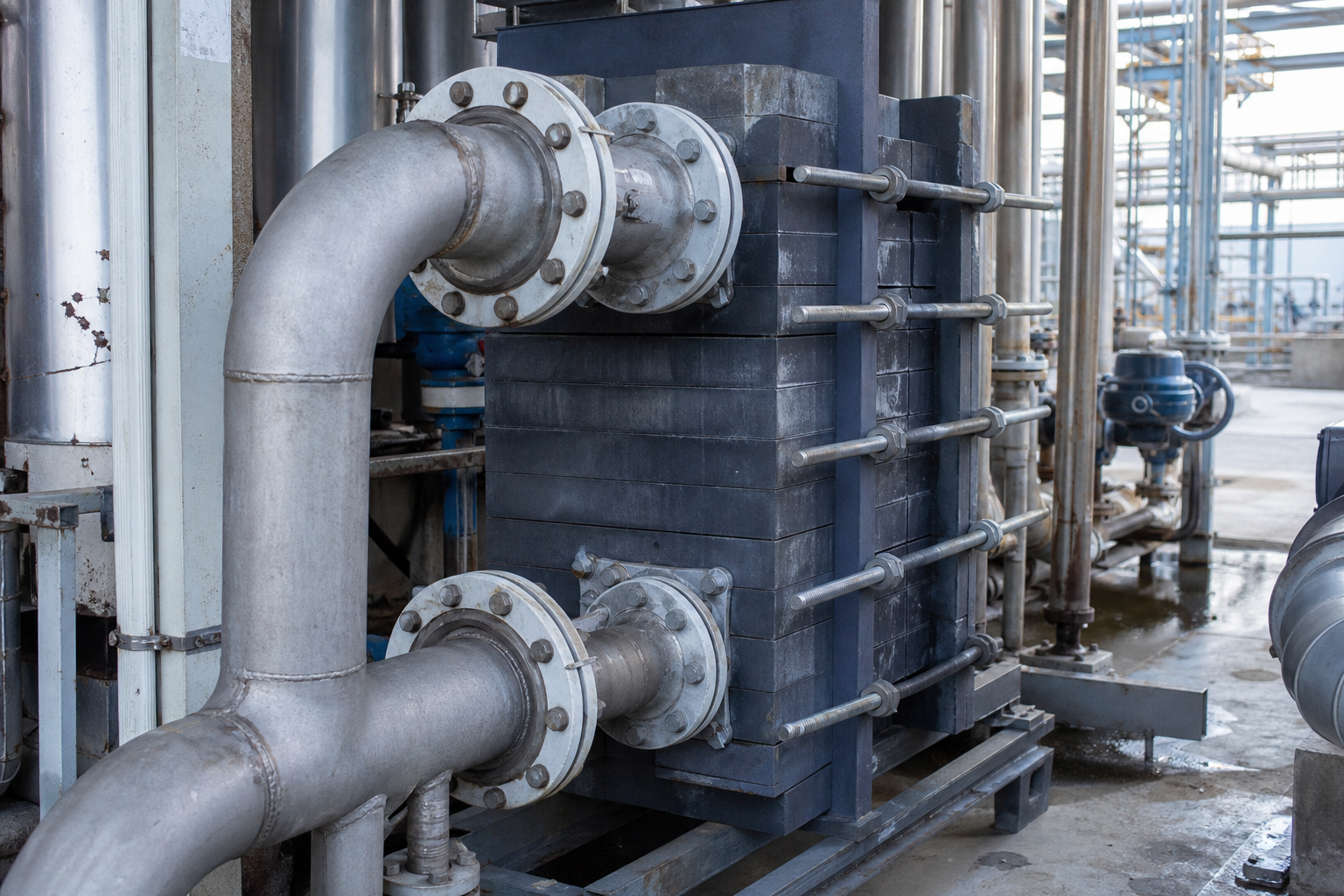
Graphite heat exchangers deserve particular attention in fluoride evaporation. They combine near-total HF immunity with high heat-transfer coefficients, and they tolerate the thermal cycling of MVR service; their limitation is mechanical fragility and pressure rating, which the process design must respect. The correct project sequence is therefore water chemistry first — speciate the fluorine, the free acid, and the companion ions — and materials selection second, because the answer for an HF-dominant liquor and a neutral fluoride-salt brine is completely different.
What the Recovered Fluorine Becomes
Crystallized fluorine has established commercial outlets, which is what separates resource recovery from waste disposal. Sodium fluosilicate and potassium fluosilicate are sellable products used in water fluoridation, opacifiers, and further fluoride chemistry; cryolite-path products return to aluminum smelting; and in battery-materials streams, lithium can be recovered ahead of the fluoride step as carbonate-bearing salts, leaving a cleaner fluoride liquor for crystallization. The choice of target crystal is set by the cation matrix already present in the wastewater — adding sodium to a fluosilicic stream yields Na₂SiF₆, while a potassium-bearing liquor points toward K₂SiF₆ — and by the local market for each product.
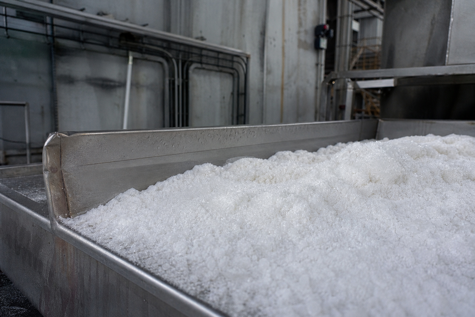
This product-selection logic matters commercially because the value of the recovered salt rarely covers the plant by itself; the business case rests on three avoided costs stacked together — hazardous waste disposal fees, discharge permit pressure, and process water purchases replaced by returned condensate. Plants that evaluate only the salt revenue underprice the project. The same stacked-benefit logic applies across zero liquid discharge systems, and the fluoride case is one of the clearest examples because untreated fluoride sludge sits in the most expensive waste category a plant can generate.
| Criterion | Lime precipitation | Evaporation–crystallization |
|---|---|---|
| Residual dissolved fluoride | Limited by CaF₂ solubility equilibrium; polishing steps needed for strict limits | Fluoride leaves with the crystal; condensate carries negligible F |
| Waste output | Hazardous CaF₂ sludge for off-site disposal | Sellable fluoride/fluosilicate salt + clean condensate |
| Water balance | Open; treated water discharged | Closed; condensate reused in scrubber/process |
| Materials of construction | Carbon steel / concrete with linings | PTFE-lined, PVDF, graphite, high-nickel alloys (HF immunity required) |
| Economics | Low CAPEX, perpetual OPEX + disposal fees | Higher CAPEX, offset by disposal savings, product value, water reuse |
Integrating Fluoride Treatment with the Host Process
The best-performing fluoride installations are designed from the gas side backward. Scrubber design determines the absorption liquor concentration that the evaporator receives; a scrubber operated for minimum water consumption delivers a richer, smaller liquor stream that shrinks the evaporation plant proportionally. Conversely, an oversized scrubber watering down the acid multiplies the evaporation duty and the energy bill. Coordinating the two disciplines — gas absorption and thermal concentration — is where the compact, economical projects come from, and it is also why retrofit fluoride plants often underperform purpose-designed ones.
For related ZLD practice on the mixed high-TDS streams that lithium and new-energy plants also generate, see our article on high-salinity wastewater ZLD and salt crystallization; the concentration and crystallization hardware is shared, with materials and crystal-chemistry being the fluoride-specific layers.
When This Route May Not Fit
Dilute, high-volume fluoride streams with a modest discharge limit are still best served by lime precipitation plus polishing – thermal treatment of a weak liquor evaporates mostly water and pays for it. Liquors dominated by high free-HF concentration belong to acid recovery or distillation routes, not to salt crystallization. Very high dissolved silica can defeat fluosilicate crystallization and blind heat exchangers, making pretreatment or a different endpoint necessary. Where no market exists for the recovered fluosilicate within hauling distance, and the crystal is itself classified as waste, the business case collapses back to disposal economics. And small, intermittent rinses from job-shop etching lines rarely justify dedicated thermal plant at all.
What Must Be Verified
Before this route is committed, verify the inputs that gate it. First, a full speciation of the water: free HF versus fluoride versus fluosilicate, companion acids, sulfates, chlorides, heavy metals, and silica level, because materials and crystal chemistry both hang on the speciation. Second, materials compatibility at the actual temperature and concentration – coupon or supplier data for graphite, PTFE-lined, PVDF, and high-nickel options – since HF corrosion rates are notoriously matrix-dependent. Third, the target product: which cation to add, which fluosilicate or cryolite-path crystal the local market will buy, and at what specification. Fourth, pilot confirmation of silica fouling rate and crystal habit. Fifth, the regulatory position on both the recovered salt and any residual streams in the specific jurisdiction.
Frequently Asked Questions
Why can’t lime precipitation remove fluoride completely?
Because CaF₂ has a finite solubility. Once the water reaches saturation with respect to calcium and fluoride ions, additional lime precipitates more solid but cannot drive dissolved fluoride below the equilibrium concentration. Strict discharge limits therefore require polishing steps — aluminum coagulation, activated alumina adsorption, or membranes — on top of precipitation.
What products can be recovered from fluoride wastewater by crystallization?
Sodium and potassium fluosilicates from fluosilicic-acid-bearing streams, cryolite-path products for aluminum smelting, and lithium salts recovered ahead of the fluoride step in battery-materials plants. The target crystal is selected by the cations already present in the liquor and by the local market for each product.
Why can’t standard stainless steel or titanium be used in fluoride evaporators?
Hydrofluoric acid — even dilute — corrodes stainless steels and titanium. Fluoride duty requires PTFE-lined steel, PVDF, glass-lined vessels, graphite heat exchangers, or selected high-nickel alloys. This is the opposite of chloride brine practice, where titanium and 2205 duplex are the default materials.
How much hazardous waste does the evaporation route eliminate?
In a documented new-energy fluorine recycling project treating waste-gas absorption liquor, hazardous waste volume was reduced by approximately 90% while the waste liquid stream achieved zero liquid discharge — fluorine was recovered as a resource instead of being precipitated as disposable CaF₂ sludge.
Is MVR or multiple-effect evaporation better for fluoride liquors?
The choice follows energy economics and liquor scale, same as any ZLD application, but with a materials constraint: MVR’s compressor and high-flux exchangers favor graphite and lined construction, which are also the HF-compatible choices. For small or intermittent absorption-liquor streams, skid-mounted multi-effect units are often the pragmatic first stage; large continuous streams justify MVR on operating cost.
To screen this route for a specific fluoride stream, share the water analysis with fluoride and silica levels, the flow rate, and the discharge or reuse target – enough for an initial process-direction assessment.