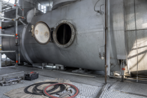
An FC crystallizer — forced-circulation crystallizer — is an externally heated, slurry-circulation type continuous evaporative crystallizer: a high-flow, low-head axial pump drives the crystal slurry out of the conical bottom of the crystallization chamber, through a shell-and-tube heat exchanger where it is warmed by 2–3°C without boiling, and back into the chamber, where the pressure drop triggers adiabatic flash evaporation and the resulting supersaturation is deposited on the surface of suspended crystals. This simple, robust loop makes the FC crystallizer the default choice for high-viscosity, fouling-prone and impurity-laden liquors — ammonium sulfate, sodium chloride, sulfate-rich ZLD brines, MSG mother liquors and high-solids food concentrates — at the cost of a relatively fine, wide-distribution crystal product (typically 0.15–0.3 mm). This article explains the structure, the working cycle, the design parameters that govern performance, and how FC units compare with DTB and OSLO crystallizers — the crystallization view. When the same loop is applied to plain evaporation-concentration duty (heat transfer, circulation, concentration without crystal product), that is the forced-circulation evaporator guide‘s territory.
What Is an FC Crystallizer and Where Does It Fit?
Classified by the way material circulates, industrial evaporative crystallizers fall into three families: external-circulation (FC) units, draft-tube-baffled (DTB) units, and fluidized-bed (OSLO) units. The FC crystallizer is the external-heating, forced-circulation member of this family: boiling does not occur in the heater, and crystal growth happens in a well-mixed slurry volume rather than in a classified fluidized bed.
That architectural choice defines the trade-off. Because the slurry is violently mixed and supersaturation is released in the liquid bulk rather than gently in a classification zone, the FC crystallizer tolerates difficult liquors — high viscosity, high solids, scaling salts, dissolved impurities — but produces crystals with a wide size distribution. When the application demands large, uniform crystals (coarse salt, large-grain ammonium sulfate), a DTB crystallizer or an OSLO crystallizer is usually the better machine; when the application values throughput, availability and fouling resistance above crystal perfection, the FC design wins.
Core Structure: Four Main Components
Every FC crystallizer is built around four elements, with the heat exchanger set outside the process vessel precisely so that it can be isolated and cleaned:

| Component | Function | Engineering Notes |
|---|---|---|
| Heat exchanger (calandria) | Heats the circulating slurry; no boiling inside the tubes | Externally mounted for easy cleaning and maintenance — critical for fouling and high-viscosity services |
| Evaporation/flash chamber | Vessel where pressure drop triggers flash evaporation and crystal growth | Conical bottom collects the slurry; vapor space sized for gentle supersaturation release |
| Riser and downcomer (circulation pipes) | Carry slurry between chamber and heater | Riser velocity kept below 1 m/s to accommodate vapor bubbles under vacuum; riser diameter slightly larger than downcomer to suppress flash boiling |
| Axial circulation pump | Drives the external loop at high flow, low head | Double mechanical seal with independent flush; abrasive-service protection at solids content up to ~30% |
How the Working Cycle Operates
The cycle proceeds in four repeating steps:
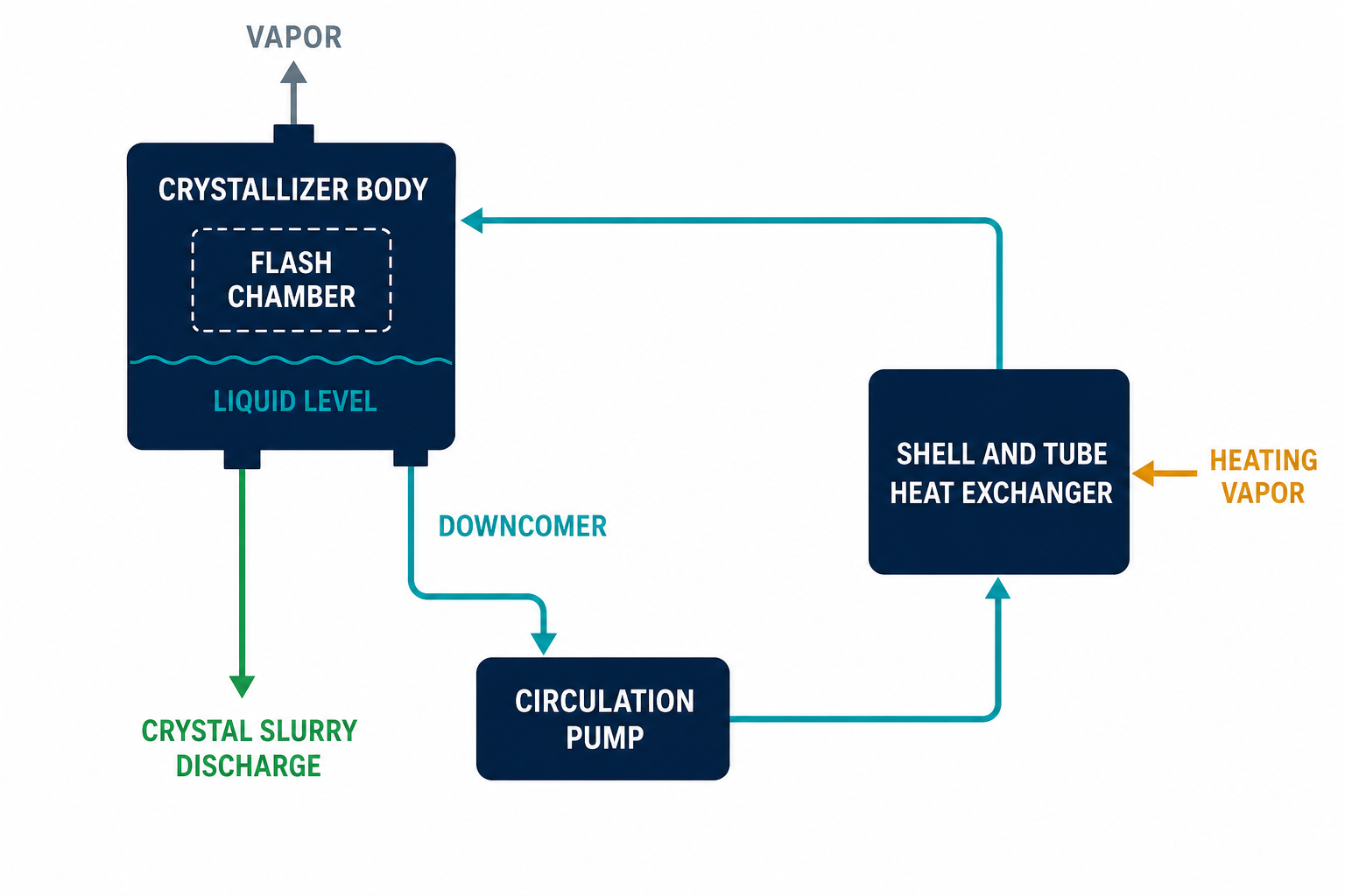
1. Withdrawal and pumping
Slurry is drawn from the conical bottom of the crystallization chamber, where the densest suspension sits, and pushed by the axial pump toward the heat exchanger. Feed liquor typically enters the loop at a low position, mixing with the recycled slurry before the heater.
2. Sensible heating without boiling
Inside the heater, the static pressure head suppresses boiling. The slurry gains a strictly limited temperature rise — typically 2–3°C, at most 6°C — so no vapor forms in the tubes and no premature crystallization fouls the heat-transfer surface.
3. Flash evaporation and supersaturation
When the heated slurry re-enters the chamber, the pressure drops below its saturation pressure. A fraction of the solvent flash-evaporates, cooling the liquor and creating a controlled supersaturation in the liquid bulk.
4. Growth on suspended crystals
That supersaturation is consumed by deposition on the enormous surface area of suspended crystals rather than by fresh nucleation — provided the loop is correctly tuned. Product slurry leaves through the upper circulation line toward dewatering, and the cycle repeats continuously.
Key Design Parameters and Why They Matter
Three parameters dominate FC crystallizer performance, and external industry references indicate they are where most projects go wrong: across 200+ international projects, roughly 65% of FC system failures trace back to underestimated boiling point elevation (BPE) or improper velocity control at the design stage — not to mechanical faults.
| Parameter | Typical Range | Consequence of Getting It Wrong |
|---|---|---|
| Tube-side velocity (heater) | 1.5–2.5 m/s (crystallizer service; FC evaporator concentration duty typically runs 2–3.5 m/s — see the FC evaporator guide) | Raising velocity ~20% lifts the heat-transfer coefficient ~15% and scours nasient crystal nuclei off the tube wall, extending CIP intervals; too low invites rapid scaling |
| Heater temperature rise | 1.5–6°C (typ. 2–3°C) | Too high: violent flash in the chamber generates excessive fines and degrades the crystal size distribution; too low: circulation flow and pump power balloon |
| Chamber liquid level above upper tube sheet | 4–6 m | Insufficient static head lets the heater outlet boil at the tube sheet, crystallizing in the ports and plugging the bundle |
| Riser / downcomer velocity | <1 m/s / 1.5–2.0 m/s | Undersized riser causes flash boiling in the return line; under low vacuum the two pipes may be equal diameter |
| Application-specific presets | High-salinity wastewater: 1.8–2.2 m/s, ΔT 3–5°C, 15–25% solids, duplex 2205 Battery-grade lithium carbonate: 2.0–2.5 m/s, ΔT 2.5–4°C, TA2 titanium Food-grade organic acids: 1.5–1.8 m/s, ΔT 3–6°C, 316L/904L |
Each liquor class has its own velocity/ΔT/materials envelope; copying a design across services is a common root cause of chronic fouling |
The velocity–temperature-rise pair is fundamentally a dynamic balance: the design task is to deliver the required heat duty at the lowest supersaturation spike the chamber can absorb. For much more on the governing relationship Q = K·A·ΔT and how fouling resistance eats the coefficient, see heat transfer and heat exchangers in evaporation systems.
Crystal Product Characteristics
The FC crystallizer produces comparatively fine crystals with a wide size distribution — typically 0.15–0.3 mm for common inorganic salts, although sulfate systems can reach 0.8–4 mm. High circulation velocity does help control supersaturation and limit secondary nucleation, but the fundamental well-mixed architecture caps how narrow the distribution can get. For environmental projects — where throughput, not single-crystal perfection, is the objective — this is an acceptable trade, and the FC design’s simpler structure, lower CAPEX, easier installation and simpler CIP make it the economical option.
FC vs DTB vs OSLO: Selection Logic
| Criterion | FC | DTB | OSLO |
|---|---|---|---|
| Crystal size | Fine, wide CSD (0.15–0.3 mm typ.) | Large, uniform | Large, very uniform (fluidized-bed classification) |
| Best-suited liquors | High viscosity, fouling-prone, impurity-laden | Clean liquors where crystal size commands premium | Clean, low-viscosity liquors needing tight classification |
| Inverse-solubility salts (Na₂SO₄, CaCO₃) | Yes — high Reynolds number (Re > 10,000) plus short thermal exposure in the heater suppress premature crystallization | Possible but less robust | Risky — scaling in the classification zone |
| Structure / CAPEX | Simplest, lowest | Moderate | Tallest, highest |
| CIP / maintenance access | Easiest (external heater) | Moderate | Hardest |
A practical rule: specify DTB or OSLO when the product is sold on crystal size and appearance; specify FC when the liquor is hostile or the product is a commodity. Many zero liquid discharge (ZLD) plants run FC crystallizers precisely because end-of-pipe brines are the dirtiest stream on site. The FC crystallizer system page covers configuration options in more depth.
Anti-Fouling Engineering Essentials
Because scaling is the FC crystallizer’s natural enemy, mature designs attack it three ways:
- Generous bend radii (R ≥ 1.5D) everywhere in the circulation loop, eliminating dead zones where slurry stagnates and crystals cement onto the wall.
- Extended vapor-phase residence time in the chamber, so supersaturation is released gently below the liquid surface instead of explosively at the flash zone. Increasing residence time by ~15% cuts fouling rate by roughly 30% (reported engineering correlation).
- An 8,000-hour continuous-run target, backed by condition monitoring, between major cleans.
Hydraulic miscalculation is unforgiving: with an unbalanced circulation design, heat-transfer efficiency can fall more than 40% within 30 days of commissioning (external industry references).
MVR Integration and Energy Economics
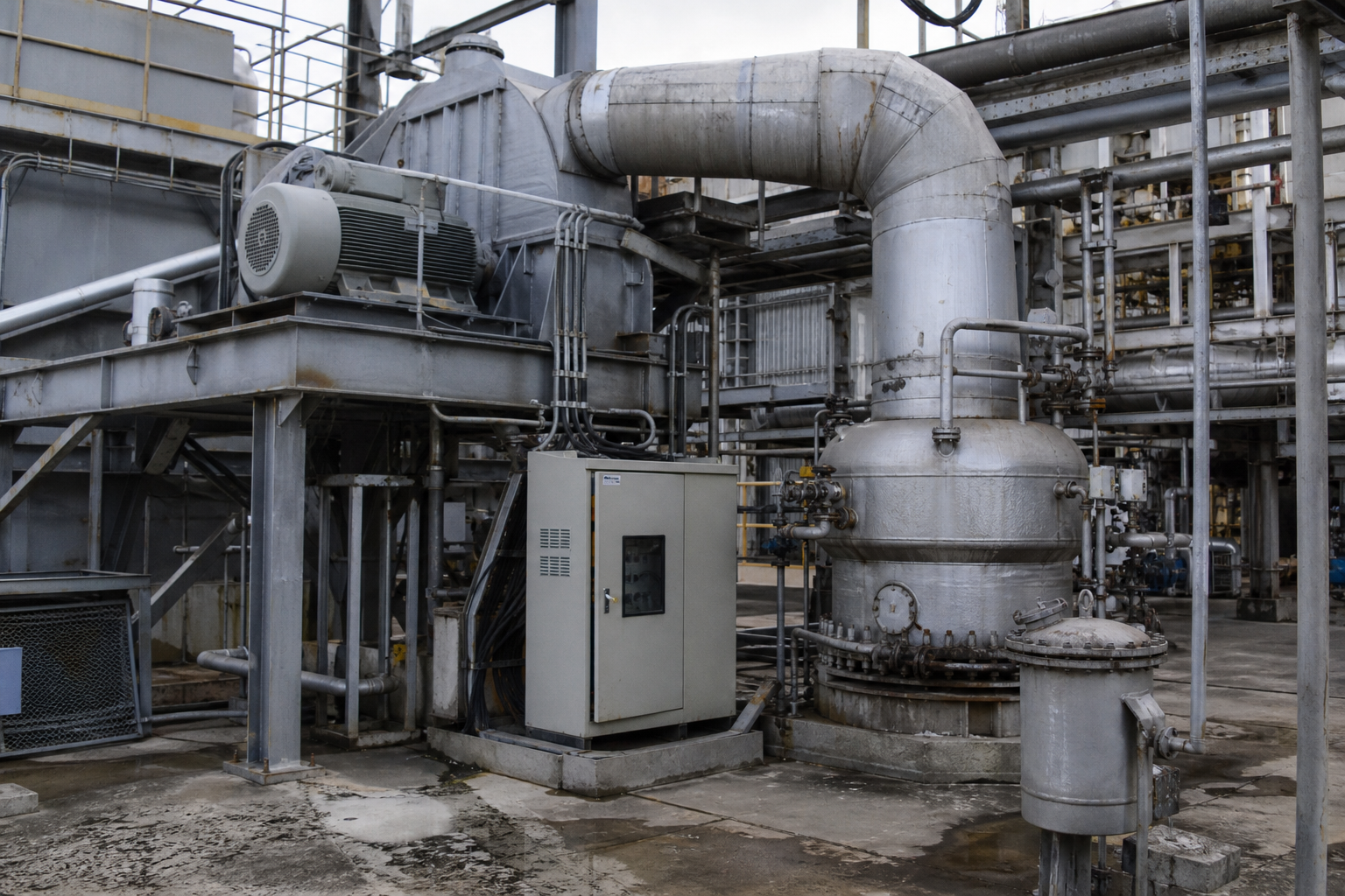
Bolting a mechanical vapor recompression (MVR) train onto an FC crystallizer converts it from a steam consumer into an electrically heated recycle loop: a centrifugal compressor lifts the secondary vapor’s pressure and temperature and returns it to the heater as the heat source. Once stabilized, the system needs essentially zero fresh steam.
Measured on an externally reported ammonium sulfate project comparing FC-MVR against a triple-effect plant:
- Live steam consumption: 0.35–0.40 t per ton of evaporated water → zero
- Electricity: 5–8 → 20–35 kWh/t of electricity, replacing the 0.35–0.40 t of live steam per ton of water that the triple-effect baseline above consumes
- OPEX: $12.5/t → $4.2/t — a ~66% reduction
- Carbon footprint: 180 → 45 kg CO₂/t
- Payback of the incremental MVR investment: 14–22 months when annual runtime exceeds 6,000 hours
One physical limit governs applicability: when the liquor’s boiling point elevation exceeds ~15°C (concentrated lithium hydroxide being one illustrative case), a single centrifugal stage cannot develop enough temperature lift, and the design must move to two-stage compression or TVR assist. Low-temperature vacuum operation at 50–70°C remains available for thermally sensitive products — see MVR evaporation systems for the compressor-side details.
Materials: Matching Metallurgy to the Liquor
- Food and pharma grades: SS316L or 2205, welds polished to Ra < 0.4 μm for hygienic service.
- High-salinity wastewater (Cl⁻ > 5,000 ppm): duplex 2205 minimum; 316L pits in this regime. 2507 where strength demands it — duplex yield strength is roughly double that of austenitic grades.
- Battery-materials and other aggressively corrosive services: TA2 titanium or Hastelloy C276. CAPEX rises ~40%, but design life extends from ~3 years to 15+ (supplier-reported comparison).
Mechanical Seals and High-Solids Service
The axial pump seal is the single most failure-prone mechanical element. Specifying a double-face, cartridge-type mechanical seal with an independent flushing circuit extends seal life from an industry-reported average near 6 months to 18 months or more. At solids content approaching 30%, abrasive wear protection on the impeller and wetted path becomes part of the base scope, not an option.
Digital Control: Three Dimensions
Modern FC trains close three control loops that operators historically ran by feel:
- Online density measurement continuously controls slurry density — a variable whose long-term impact is commonly underestimated in external industry references.
- PLC control of vacuum and circulation flow holds the system inside the metastable zone; supersaturation swings beyond ~5% trigger runaway nucleation and a fines avalanche.
- IIoT remote diagnostics flag heat-transfer-coefficient decay ~48 hours before CIP becomes mandatory, cutting unplanned downtime by ~35% (supplier-reported figures).
Typical Applications
- Inorganic salts: ammonium sulfate and sodium chloride crystallization, including salt separation and fractionation trains on mixed brines
- ZLD back-ends: sulfate and mixed-salt crystallization as the final solids step in zero liquid discharge
- Fermentation: monosodium glutamate and glutamic acid second mother liquors
- Food: tomato paste, bone broth and other high-viscosity, fouling-prone concentrates where the forced-circulation mechanism prevents tube blockage
- General evaporation duties: the FC evaporator variant (without crystallization emphasis) concentrates acids, alkalis, pharmaceutical extracts and wastewater — the forced-circulation evaporator guide covers that side of the family; single-effect FC units span chemicals, food, pharma, environmental and resource-recovery service
Conclusion
The FC crystallizer earns its place as the industrial workhorse by doing the difficult jobs reliably: dirty, viscous, scaling liquors processed continuously in a mechanically simple loop. Success is decided at the design stage — tube velocity, heater temperature rise, liquid level above the tube sheet, an honest BPE estimate — and increasingly by whether the unit is paired with MVR to eliminate steam. Get those right, and the same architecture that runs 8,000 hours between cleans also delivers the lowest operating cost per ton of water evaporated.

FAQ
What does FC stand for in an FC crystallizer?
FC stands for forced circulation. An axial pump continuously circulates the crystal slurry through an external heat exchanger and back into the flash chamber — distinguishing it from natural-circulation designs and from DTB/OSLO crystallizers, which classify crystals internally.
What crystal size does an FC crystallizer produce?
Typically 0.15–0.3 mm for common inorganic salts, with a relatively wide size distribution. Sulfate systems can yield 0.8–4 mm. If the product is sold on large, uniform crystals, a DTB or OSLO design is usually specified instead.
Why must the liquid level stay 4–6 m above the heat exchanger tube sheet?
The static head suppresses boiling at the heater outlet. If the level drops, the slurry flashes at the tube ports, crystals deposit there, and the bundle plugs — one of the most common causes of forced outages in badly controlled FC plants.
Can an FC crystallizer be combined with MVR?
Yes, and it is now standard practice for energy-intensive duties. FC-MVR replaces 0.35–0.40 t of live steam per ton of evaporated water with 20–35 kWh/t of electricity, cutting OPEX by roughly 66% versus a triple-effect baseline. When boiling point elevation exceeds ~15°C, two-stage compression or TVR assist is required.
Which is better for high-salinity wastewater: FC or DTB?
FC. ZLD brines are typically viscous, impurity-laden and scaling-prone — exactly the conditions the FC loop tolerates. DTB and OSLO units prefer clean, low-viscosity liquors where their superior crystal classification has value.