Heat pump evaporators and thermal vapor recompression (TVR) systems cut evaporation energy cost by upgrading heat you already have instead of burning fresh fuel: heat pump evaporators use an electrically driven refrigeration cycle to lift low-grade heat from ambient air, water, or process waste streams up to evaporation temperature — with externally reported savings of 30–50% of the energy a conventional evaporator would consume — while TVR ejectors use a modest flow of high-pressure motive steam to entrain and recompress low-pressure secondary vapor for reuse, with no moving parts at all. Around these two, waste-heat-driven multi-effect distillation (MED) recovers hot water, thermal oil, and flue gas directly as the driving heat of the first effect. This guide explains how each technology works, where each wins, and how the three combine into the triple-saving architecture used in modern evaporation-plant retrofits.
What Is a Heat Pump Evaporator?
A heat pump evaporator replaces primary energy — gas firing or fresh steam — with moved heat. Instead of generating heat at evaporation temperature, it extracts low-temperature heat from the surroundings (air, water, or industrial waste heat) and delivers it to the process side at useful temperature. The thermodynamic work done is moving heat up a temperature ladder, which costs a fraction of generating that heat from fuel.
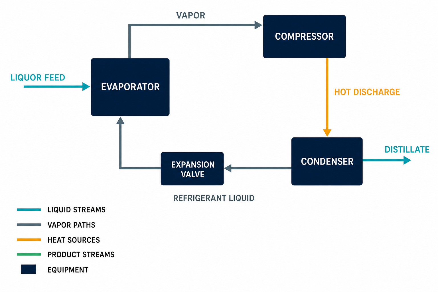
The refrigeration cycle, run in reverse
The machine is a standard refrigeration circuit with four components — familiar from HVAC, scaled for industry:
- Evaporator — low-temperature refrigerant boils, absorbing heat from the low-grade source (air, water, waste stream);
- Compressor — electrically driven, it raises the refrigerant’s pressure and temperature;
- Condenser — the hot refrigerant releases its heat to the process side, heating the liquid being evaporated;
- Expansion valve — the refrigerant throttles back down in pressure and returns to the evaporator, closing the loop.
A chiller and a heat pump evaporator share this cycle; only the direction of benefit differs. The chiller values the cold side, the heat pump evaporator values the hot side.
MVR: Vapor Recompression in the Same Family
Mechanical vapor recompression is the most widespread industrial expression of heat-pump thinking. An electrically driven compressor takes the secondary vapor boiling off the process, raises its temperature and pressure, and returns it as the evaporator’s main heating steam — a closed loop of evaporation and condensation recirculating latent heat instead of venting it to a condenser. Typical applications include industrial concentration and drying, seawater desalination, and ZLD wastewater recovery; the operating principles and equipment are covered in detail on the MVR technology page.
TVR: Steam Ejectors for Vapor Recompression
Thermal vapor recompression achieves the same goal — raising secondary vapor back to useful temperature — with a steam ejector instead of a compressor:
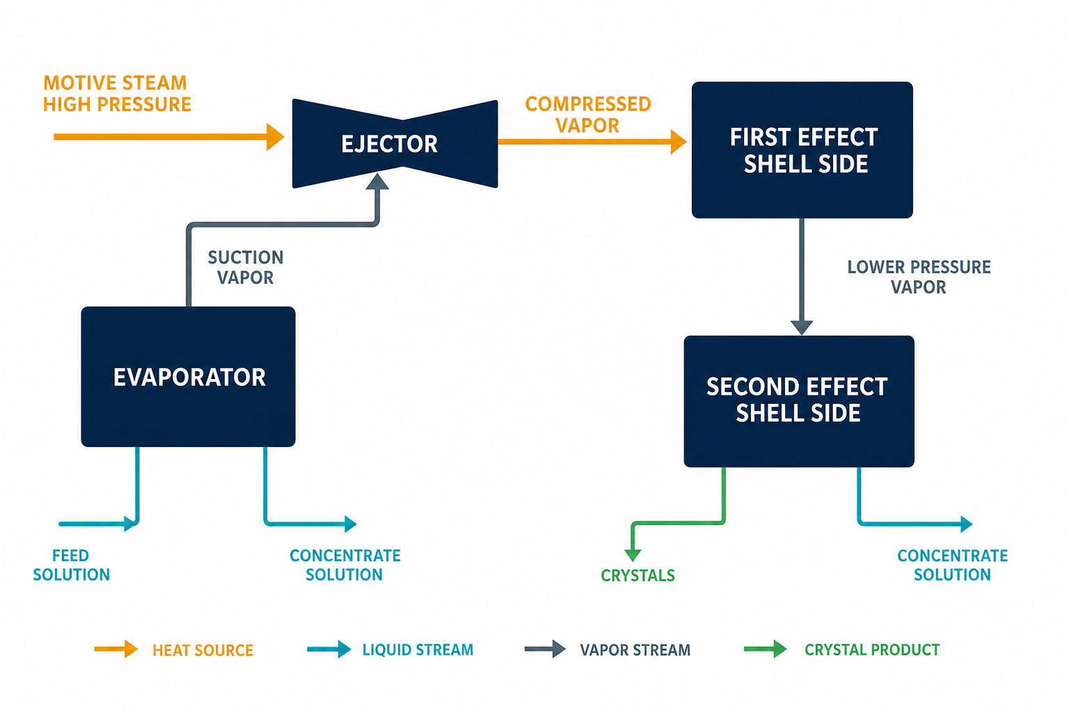
- A small flow of high-pressure motive steam accelerates through a nozzle, dropping in pressure and gaining velocity;
- The jet entrains the plant’s low-pressure secondary vapor into the mixing chamber;
- The mixture recovers pressure through a diffuser and re-enters the evaporator’s heating side at intermediate temperature.
The ejector is effectively a mechanical steam pump with no moving parts — nothing rotates, nothing wears, and maintenance reduces to keeping the nozzle clean. The trade-offs are equally structural: TVR requires a genuinely available high-pressure steam source on site, and its temperature lift is limited compared with a mechanical compressor, so it suits plants with generous steam capacity and modest compression duty. Where those conditions hold, TVR delivers recompression at a fraction of the capital cost of an MVR machine.
TVR vs. MVR vs. Waste-Heat MED: Choosing the Recovery Route
| Criterion | TVR (thermal recompression) | MVR (mechanical recompression) | Waste-heat MED |
|---|---|---|---|
| Driving energy | High-pressure motive steam | Electricity | Hot water / thermal oil / flue gas |
| Moving parts | None (ejector) | Compressor (rotating machine) | Pumps only |
| Maintenance burden | Very low | Moderate — compressor quality is critical | Low |
| Temperature lift | Limited | Higher; limited by boiling-point elevation | Set by waste-heat temperature |
| Site requirement | Existing HP steam network | Reliable electric supply | Continuous low-grade heat source |
| Best fit | Steam-rich plants avoiding compressor CAPEX | High energy prices, no steam, tight footprint | Food, ethanol, plants with hot oil or flue gas |
All three routes are constrained by the same physics — boiling-point elevation and available temperature difference — and all three can coexist in one plant. For the underlying multi-effect architecture that waste-heat systems build on, see the multi-effect evaporation overview.
The Industrial Waste-Heat Inventory
Waste-heat evaporation is only as good as the heat inventory behind it. The recoverable low-grade sources found across process industries:
| Waste-heat source | Typical form | Use in evaporation plant |
|---|---|---|
| Low-pressure vented / flash steam | Steam at near-atmospheric pressure | Direct drive of first effect or ejector suction |
| Boiler blowdown water | Hot pressurized water | Flashed to steam or routed through preheater/first effect |
| Hot thermal oil loops | Circulating oil, process-side reject | First-effect heating via oil-to-brine exchanger |
| Furnace and kiln flue gas | Hot gas stream | First-effect heating through gas exchanger |
| Contaminated condensate | Hot water unsuitable for boiler return | Evaporation driving heat — recovered as clean distillate |
| Hot process effluent | High-temperature liquid waste | Heat exchange before treatment |
Waste-Heat MED in Practice
A waste-heat MED plant needs no steam boiler: hot water, oil, or flue gas enters the first effect’s heat exchanger directly as the driving source, and each subsequent effect runs on the vapor from the one before. Because lower evaporation temperature preserves more recoverable heat, these plants are designed to run under vacuum at low top brine temperatures.
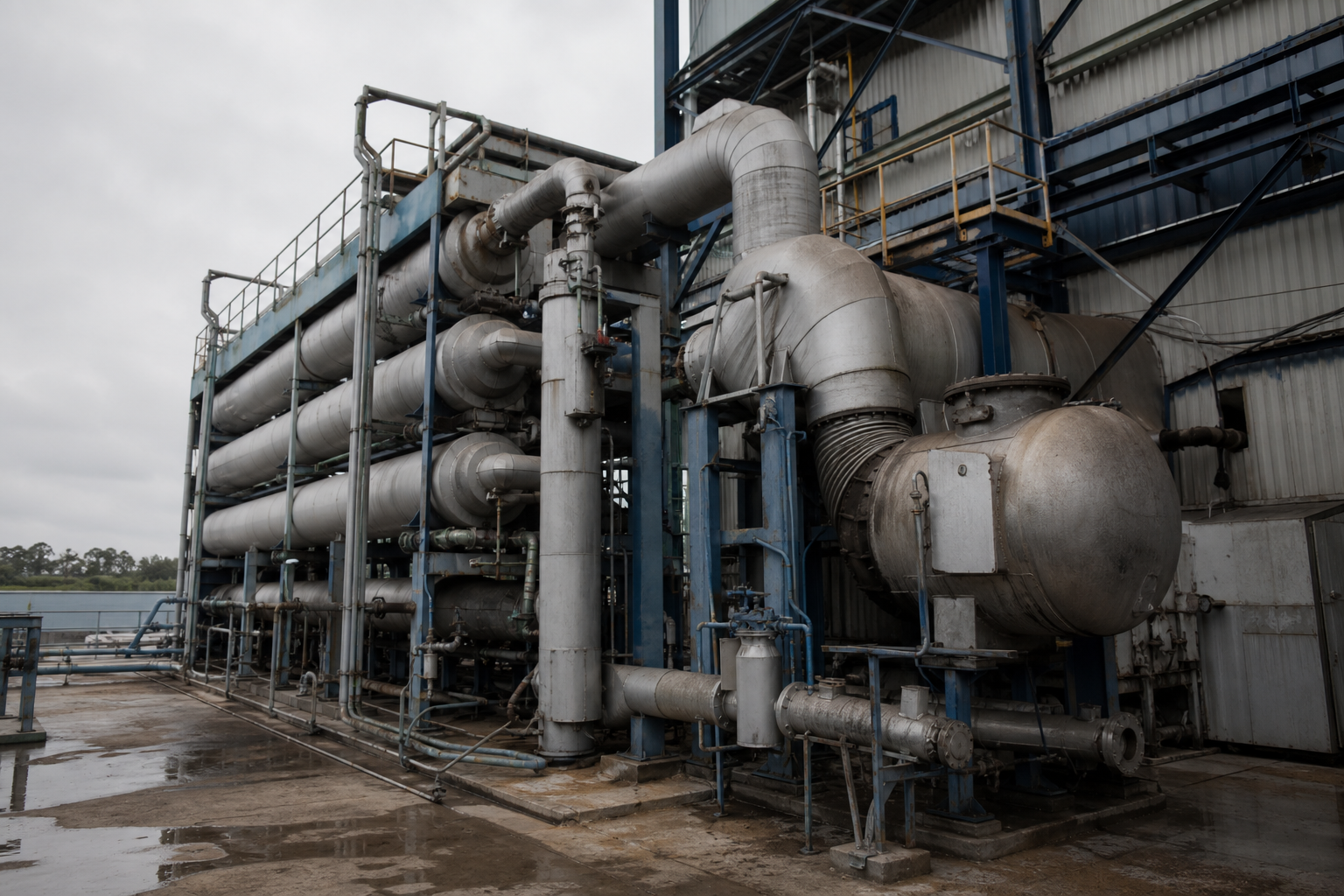
The configuration menu matches standard evaporator practice — falling-film MED, forced-circulation MED, mixed designs, and rising-film MED — selected by scaling tendency, viscosity, and product requirements, at scales spanning the published supplier range of 1 to 100 t/h of evaporation capacity. The food and beverage sector is the most committed user: fruit juice, whey, brewer’s wort, corn steep water, sugar-beet juice, yeast, serum, collagen, and starch concentrators routinely run on recovered heat, because their low-temperature sensitivity and continuous operation reward both the gentle thermal profile and the near-zero marginal energy cost.
Beyond Evaporation: Heat Pump Distillation and ORC
Two related technologies complete the waste-heat toolbox for separation plants:
Heat pump distillation (HPD)
In distillation columns, heat is rejected at the top (condenser) and demanded at the bottom (reboiler) — a perfect heat-pump application. A compression refrigeration cycle running between reboiler and condenser closes the loop: refrigerant vapor is compressed, condenses in the reboiler delivering heat to the column bottom, throttles through the expansion valve, then evaporates in the overhead condenser absorbing the tower’s latent heat — coupling column top and bottom thermally. The wider HPD family includes internally heat-integrated columns (IPC), separator heat-pump distillation, and absorption heat-pump distillation. Industry assessments rank heat pump distillation as the largest energy-saving opportunity in chemical separations after conventional distillation optimization itself.
Organic Rankine Cycle (ORC)
Where recovered heat cannot be used thermally, ORC converts it to electricity: the organic working fluid (commonly R245fa, R134a, or R600a) evaporates against the waste-heat stream, expands through a turbine driving a generator, condenses, and is pumped back — four components mirroring the heat pump’s, run to produce power instead of moving heat. Power plants and industrial sites use ORC to monetize exhaust and reject streams that would otherwise be lost.
Quantified Benefits of Heat Pump Evaporation
Externally reported operating experience with heat pump evaporators across wastewater, desalination, and chemical concentration duty aggregates to a consistent benefit set:
- Energy savings of 30–50% versus fuel- or steam-fired evaporation at equivalent duty;
- Reduced carbon footprint — heat is moved, not generated; and when the grid decarbonizes or solar supplies the compressor, the process follows;
- Soft-start motors reduce electrical network stress compared with across-the-line starting of large thermal-plant auxiliaries;
- Longer equipment life and lower maintenance from lower-temperature operation and fewer moving parts in the heat-delivery loop;
- Closed-loop operation approaching zero liquid discharge of the evaporator itself — distillate recycles, residue concentrates;
- Compact, quiet installations suited to space-constrained or urban sites;
- Policy alignment — heat pump projects frequently qualify for government energy-efficiency subsidies and tax credits, improving project economics beyond the energy bill.
The Triple-Saving Architecture
The deepest retrofits do not choose between these technologies — they stack them. A modern evaporation-station energy concept layers three recovery mechanisms:
- Waste-heat MED absorbs the plant’s low-grade heat (hot water, oil, flue gas) as free first-effect driving energy;
- TVR or MVR recompression upgrades the resulting secondary vapor — thermal recompression where steam is rich, mechanical where electricity is favored — multiplying the effective energy of every joule already paid for;
- ORC power generation converts whatever surplus heat remains after the thermal stages into electricity for the plant’s pumps and compressors.
Plants designing this way treat energy as a closed internal economy — and the same logic drives the energy retrofit and decarbonization solutions (illustrative application), where recompression and waste-heat recovery are evaluated against a site’s full utility balance. For matching the evaporator type itself to your fluid and duty, see the evaporator types comparison.
Process Modules of a Recovery Retrofit
| Module | Function | Typical Equipment | What It Replaces |
|---|---|---|---|
| Heat-source side | Capture low-grade waste heat and deliver it to the first effect | Flash vessels, oil-to-liquor and gas-to-liquor exchangers, contaminated-condensate recovery | Boiler steam to the first effect |
| Heat pump side | Lift ambient or waste heat up to evaporation temperature | Refrigeration cycle: source evaporator, compressor, process condenser, expansion valve | Fuel firing or fresh steam |
| Recovery side (thermal) | Upgrade low-pressure secondary vapor using motive steam | TVR ejector set with motive-pressure control | An additional effect of heat-transfer area |
| Recovery side (mechanical) | Upgrade secondary vapor using electricity | MVR compressor, vapor pipework, seals and control system | Live steam plus condenser duty |
| Power side | Convert residual heat into electricity | ORC skid: evaporator, turbine-generator, condenser, working-fluid pump | Purchased grid power for auxiliaries |
When This Route May Not Fit
Recovery economics depend on what a site already has, and the combinations that defeat them are predictable. A plant with no low-grade waste-heat source and expensive electricity gains little from a heat pump evaporator, because the compressor pays retail power prices to replace steam the site never had to buy. A site that is both steam-poor and electrically constrained has no recovery route at all until one utility is secured: TVR still needs high-pressure motive steam, MVR still needs a reliable grid connection, and waste-heat MED still needs heat somebody is already rejecting. Intermittent waste heat — batch flue gas, occasional blowdown — cannot support continuous evaporation duty without thermal buffering that often erodes the saving. And ORC generation only earns its place where recovered heat exceeds what MED and recompression can absorb; at small temperature lifts and small duties its capital cost per kilowatt rarely clears.
What Must Be Verified
Four checks anchor the decision before any of these routes is committed. First, a measured waste-heat inventory: source, temperature, continuity, and cleanliness — a fouling flue-gas stream is a different project from clean hot condensate. Second, the local steam-to-electricity price ratio, which decides between thermal and mechanical recompression. Third, the boiling-point elevation of the actual liquor, because it caps the temperature lift any compressor or ejector can economically deliver. Fourth, the duty profile — continuous or batch — which determines whether recovered heat can actually be absorbed at the moment it appears.
FAQ
What is the difference between TVR and MVR?
Both recompress secondary vapor for reuse as heating steam. TVR does it thermally — a high-pressure steam ejector entrains and re-pressurizes the vapor, with no moving parts, low maintenance, and limited temperature lift, requiring an existing high-pressure steam source. MVR does it mechanically — an electric compressor delivers higher lift and steady-state operation with essentially zero fresh steam, at higher capital cost and dependence on compressor reliability.
How much energy does a heat pump evaporator save?
Typically 30–50% compared with conventional fuel- or steam-fired evaporation, because the system moves existing heat up the temperature ladder instead of generating new heat. Additional savings come from closed-loop distillate recovery and avoided cooling utilities.
Can waste heat really drive an evaporator without a steam boiler?
Yes. Waste-heat MED plants take hot water, thermal oil, or flue gas directly into the first effect’s heat exchanger as the driving heat source. The lower the evaporation temperature design, the more heat remains recoverable — plants across the published supplier range of 1 to 100 t/h evaporation capacity operate this way, most commonly in food and beverage concentration.
Which industries benefit most from waste-heat evaporation?
Food and beverage is the leading adopter — juice, whey, brewer’s wort, corn steep water, sugar-beet juice, yeast, serum, collagen, and starch plants all concentrate continuously with low-temperature sensitivity. Any site with vent steam, hot oil, flue gas, or contaminated hot condensate — ethanol, chemicals, power — holds the same raw material.
What is an ORC and where does it fit?
An Organic Rankine Cycle converts low-grade waste heat into electricity using an organic working fluid (R245fa, R134a, R600a) in a four-component loop: evaporator, turbine-generator, condenser, and pump. It sits at the end of the recovery chain — after MED and recompression have taken what they can use — turning residual heat into power for plant auxiliaries.