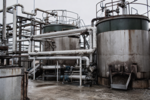
A DTB (draft-tube-baffle) crystallizer is the industry’s high-performance internal-circulation machine for large, uniform, high-purity crystals: a central draft tube with a low-speed axial impeller drives slurry up and around inside one vessel, while an annular baffle shields a quiet clarifying zone that removes fines from the growth circuit. In industry-reported figures, the architecture delivers 1.0–3.0 mm crystals with coefficient of variation under 20%, runs 10–30% below forced-circulation machines on energy, extends cleaning cycles by 50% or more, and pays back its premium in 3–5 years versus 6–8 for conventional systems. This guide covers the components, the six-step working cycle, the three operating parameters that decide crystal quality, and the applications — from food-grade salt to antibiotic APIs — where DTB is the correct answer.
Position in the Crystallizer Family
Classified by the way material circulates, three crystallizer structures dominate industrial practice: forced-circulation (FC) units with external pump loops, DTB units with internal draft-tube circulation, and Oslo fluidized-bed units where crystals grow in a separate suspension zone. DTB exists for one demand: big, uniform, pure crystals — gourmet salt, pharmaceutical-grade sodium sulfate, premium MSG (illustrative applications) — where traditional agitated vessels drown in secondary nucleation and deliver fines-laden product that dries poorly and reprocesses expensively. The comparative picture across all three, including crystal-size bands and maintenance burden, is laid out in the industrial crystallizer selection guide.
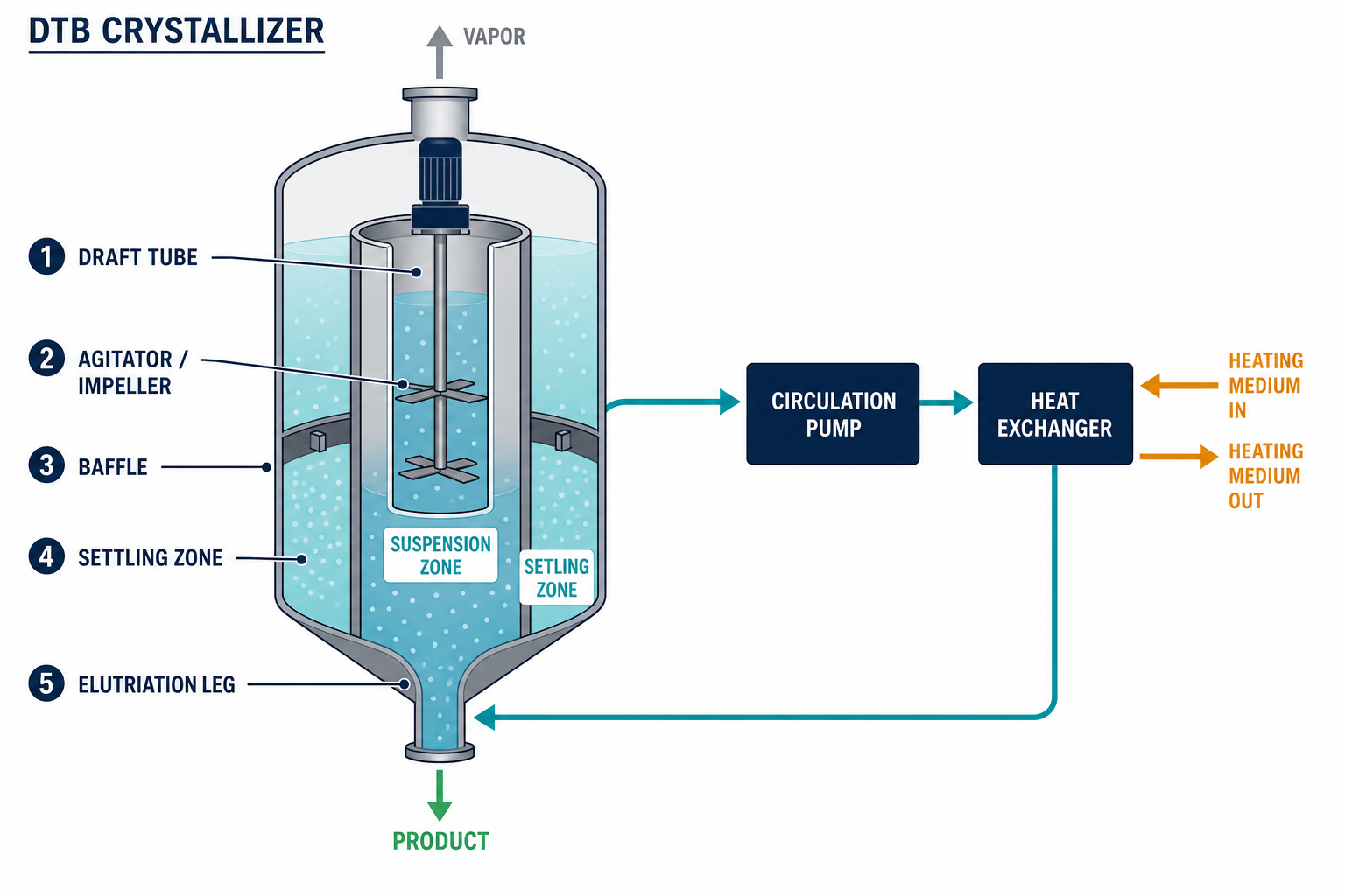
The Five Components
- Draft tube — the central cylinder that channels slurry upward, creating a strong, well-defined internal circulation loop.
- Annular baffle — the outer ring that isolates a settling/clarifying zone from the agitated growth zone; this is the feature that puts “B” in DTB.
- Axial-flow pump or low-speed propeller — mounted on the draft tube; high flow at low head, which circulates gently compared with FC’s high-shear external pumps.
- Vacuum evaporation or cooling system — generates supersaturation at the boiling surface or through the cooled wall.
- Elutriation column — the bottom leg that hydraulically classifies product: undersized crystals return to the growth zone, on-spec crystals leave as product.
The Working Cycle, Step by Step
- Hot saturated feed enters continuously at the bottom of the circulation zone.
- Feed mixes with fines-laden mother liquor and passes through the heater (evaporative duty) or cooling surface.
- The low-speed propeller in the draft tube lifts the mixture upward through the tube.
- Near the liquid surface, evaporation or cooling generates supersaturation, and solute deposits onto the suspended crystals, which grow in place.
- The baffle-separated annular zone quiets: coarse crystals settle toward the bottom while excess fines leave with mother liquor (or dissolve), keeping the growth-zone population clean.
- Bottom slurry enters the elutriation column; small crystals are returned for more growth, and product-size crystals are discharged.
Crystallization, classification, and clarification therefore happen simultaneously in one vessel — three unit operations the design folds together.
Why the Crystals Come Out Big and Uniform
Two mechanisms do the work. First, the baffle zone intercepts fines before they re-enter the growth region, cutting secondary nucleation hard — the fines that would otherwise proliferate and steal supersaturation are continuously removed. Second, the draft tube maintains a uniform, gently circulated suspension where every crystal sees the same supersaturation history. Suppliers quote 600–1200 µm as the reliable production band in standard service, extending to 1.0–3.0 mm average with CV under 20% in optimized evaporative duty — enough size and consistency that downstream centrifuging, washing, and drying stop being the bottlenecks they are with fine, wide-distribution product. Plants running wide size distributions routinely burn 5–15% of energy and labor on re-classifying and redissolving off-spec material; DTB architecture attacks that waste at the source.
The Three Operating Parameters That Set Quality
| Parameter | Control target | What happens when it drifts |
|---|---|---|
| Circulation velocity in draft tube | 1.5–3.0 m/s, VFD pump with 0.1 m/s resolution | Too high: shear breakage and secondary nucleation. Too low: crystals settle and pack. |
| Temperature / supersaturation | ±0.1 °C stability via PID coordinating steam, heating, and cooling water | Even slight swings trip burst nucleation and flood the distribution with fines. |
| Seeding | High-purity seed, narrow 0.1–0.3 mm cut, loaded to 10–20 wt% total suspended solids | No seed: uncontrolled nucleation. Dirty seed: impurities and wide distribution. |
The temperature row deserves emphasis: a DTB is a precision instrument by intent. Plants that succeed with the technology instrument it like one; plants that treat supersaturation as a manual adjustment get stirred-tank results at DTB prices.
Economics Against Alternatives
Compared with forced-circulation crystallizers on equivalent duty (industry-reported comparisons):
- Energy 10–30% lower — the axial-flow pump moves high volume at low head, cutting hydraulic losses that FC’s high-head pumps pay for.
- Cleaning cycles extended by more than 50%: uniform velocities eliminate the hot spots and surface crystal build-up that force washdowns.
- Stable operation across 2–300 m³/h capacity range.
- Return on investment in 3–5 years, versus 6–8 years for conventional systems — driven by the avoided reprocessing and energy.
On evaporative duty the remaining energy line compresses further with multi-effect or MVR integration, which typically cuts evaporation energy 20–30%; the architecture is described on the MVR technology page.
Case Study: Sodium Sulfate at a Chlor-Alkali Plant
A chlor-alkali producer (illustrative application, external industry reference) was dehydrating high-purity sodium sulfate through an FC crystallizer: average crystal size 0.6 mm, excessive fines, difficult drying. The replacement — a 250 m³ DTB body — delivered average crystal size 1.2 mm, product qualification rate up 18%, electricity consumption down 12.5%, cleaning interval stretched from 15 to 25 days, and throughput up 66%. The mechanism behind every number is the same: fewer fines, more uniform growth, less time washing and reprocessing. Sodium-class salts are natural DTB territory; the salt-specific process chain is detailed for ammonium sulfate crystallization (illustrative application) in its own write-up.
Multi-Stage DTB Trains for Purity
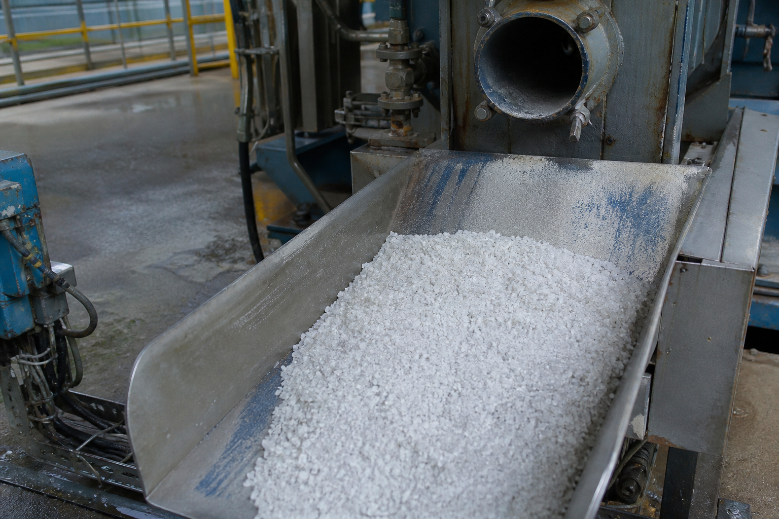
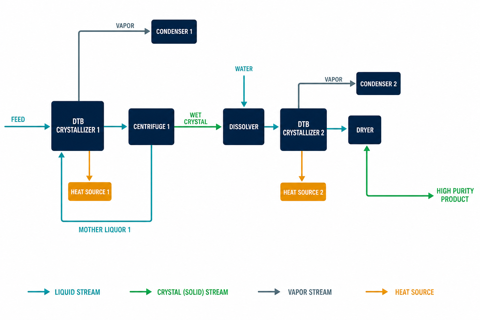
Where a single body cannot reach the product specification, DTB units stage well. Multiple bodies in series, each holding its own supersaturation and slurry density, progressively upgrade crystal purity — the arrangement that carries lithium carbonate plants (illustrative application) from 99.5% to battery-grade 99.9%, and that sugar refineries use for similar stepwise purification. Staging also decouples throughput from residence time: each body keeps its crystal population long enough to reach target size, while the train as a whole carries full plant flow. Between stages, mother-liquor advance and seed management let the engineer tune where nucleation happens and where growth dominates — the same fines-control logic as the single body, applied at train scale. Against the alternative of pushing one oversized vessel past its control envelope, staged DTB duty keeps every body inside the metastable comfort zone where crystal quality actually lives.
DTB or Oslo? The Border Between the Two
| Dimension | DTB | Oslo |
|---|---|---|
| Growth environment | Internal circulation; growth, classification, and clarification in one vessel | Separate fluidized-bed zone; supersaturation generated apart and released through the bed |
| Crystal size ceiling | 1.0–3.0 mm typical | 2–5 mm, CV < 5% |
| Structure and footprint | Simpler, more compact | Taller, more complex, tighter hydraulic control |
| High evaporation load | Handles it well | More constrained by fluidization limits |
| Choose when | Capacity, simplicity, and robustness matter at good crystal quality | Maximum size uniformity and purity justify complexity |
The working rule: pursue Oslo when the product is defined by its crystal perfection; pursue DTB when it is defined by tonnage at solid quality. Full Oslo treatment in the Oslo crystallizer guide.
Anti-Fouling and Anti-Blockage Practice
Baffle-zone blockage — the classic DTB failure mode — is prevented three ways: hold feed concentration and temperature steady so localized supersaturation spikes never occur; keep the axial pump running smoothly (its curve is the suspension’s heartbeat); and flush deposits periodically at high flow. For scaling-prone feeds, the high internal wall velocity continuously sweeps surfaces. High-viscosity and inverted-solubility materials need steam pulsing or chemical cleaning built into the design from the start. The general anti-fouling toolkit — forced circulation, supersaturation control, polished surfaces, scrapers — is surveyed on the crystallization technology page.
Where DTB Machines Work
- Food: sucrose and sweeteners, food-grade salt, MSG.
- Pharmaceutical: antibiotics and specialty APIs — where the baffle zone’s fines control protects crystal specification batch after batch.
- Inorganic chemicals: potassium nitrate, ammonium sulfate, citric acid.
- Process methods: the same body executes vacuum-cooling, evaporative, direct-contact-freezing, and reaction crystallization; the DP variant (counter-rotating external blades) pushes size further at reduced secondary nucleation.
Laboratory DTB: The Scale-Up Bridge
Integrated laboratory DTB systems at 5–200 L/h — supplied with steam generator, chiller, vacuum system, and downstream centrifuge and dryer — carry a process from basic research (5–20 L) through development (20–100 L) to pilot production (100–200 L) with the same architecture as the plant unit. The value is risk transfer: mapping metastable zone, growth kinetics, and seed strategy at bench scale is what turns a 250 m³ installation into a success rather than a scale-up experiment. Wetted materials run SS304/316L for food and GMP duty, with duplex, titanium, and SMO 254 for corrosive service; QA practice includes ASTM-traceable materials, mirror finishes to Ra ≤ 0.4 μm, and FAT/SAT protocols.
FAQ
What does DTB stand for in a crystallizer?
Draft-tube-baffle. The draft tube is the central cylinder the impeller circulates slurry through; the baffle is the annular ring that isolates a quiet clarifying zone where fines are removed. Together they suppress secondary nucleation and grow large uniform crystals.
What crystal size can a DTB crystallizer produce?
Typically 600–1200 µm in standard service, extending to 1.0–3.0 mm average with coefficient of variation under 20% in optimized duty. A chlor-alkali sodium sulfate case moved from 0.6 mm (FC) to 1.2 mm average after conversion.
How does DTB compare with forced circulation?
DTB uses internal low-shear circulation and produces larger, more uniform crystals; FC uses an external high-head pump loop, produces finer crystals, and costs 10–30% more in energy. FC remains preferred for drying-out duty and severe scaling feeds where robustness outranks crystal quality.
Which operating parameter matters most in DTB operation?
Temperature/supersaturation stability — hold it within ±0.1 °C. Burst nucleation from even small temperature swings floods the crystal size distribution with fines. Circulation velocity (1.5–3.0 m/s in the draft tube) and disciplined seeding (0.1–0.3 mm, 10–20 wt%) complete the set.
Can a DTB crystallizer run different crystallization methods?
Yes. The same body executes vacuum-cooling, evaporative, direct-contact-freezing, and reaction crystallization. The DP variant adds counter-rotating blades outside the draft tube to enlarge crystal size and raise capacity further.