EvapCryst logo

MVR — Mechanical Vapor Recompression Evaporation Systems

A mechanical compressor raises the pressure and saturation temperature of evaporated vapor so it becomes the heating steam for the same effect. Electrically driven, no live steam in steady state — the lowest-operating-cost evaporation route where grid power is available and steam is expensive.

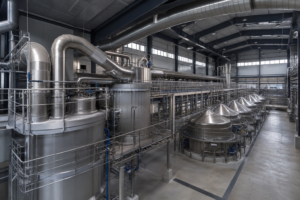
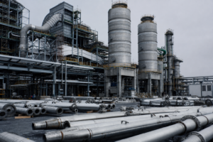
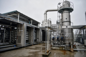
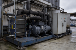
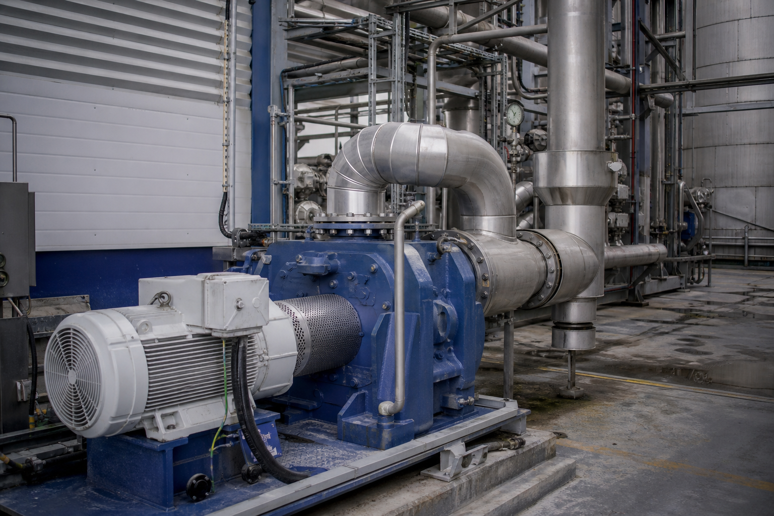
MVR mechanical vapor recompression evaporation system with steam compressor
At a Glance

Four Numbers That Define MVR

Reference ranges under typical operating conditions — where your project lands inside each range depends on the variables in the energy determinants table.

Specific Energy
15–25 kWh/t
per tonne of water evaporated, electrical only — depends on feed TDS, boiling-point rise and compressor type
Live Steam
0 steady-state
no live steam consumption in steady-state operation; small amount of motive steam only for start-up
Compressor Efficiency
75–85%
isentropic efficiency, typically for centrifugal compressors; lower for roots-type
Electrical Duty
200 kW–2 MW+
compressor rating for industrial-scale plants, at 400 V or 690 V 3-phase supply
Working Principle

The MVR Vapor Loop

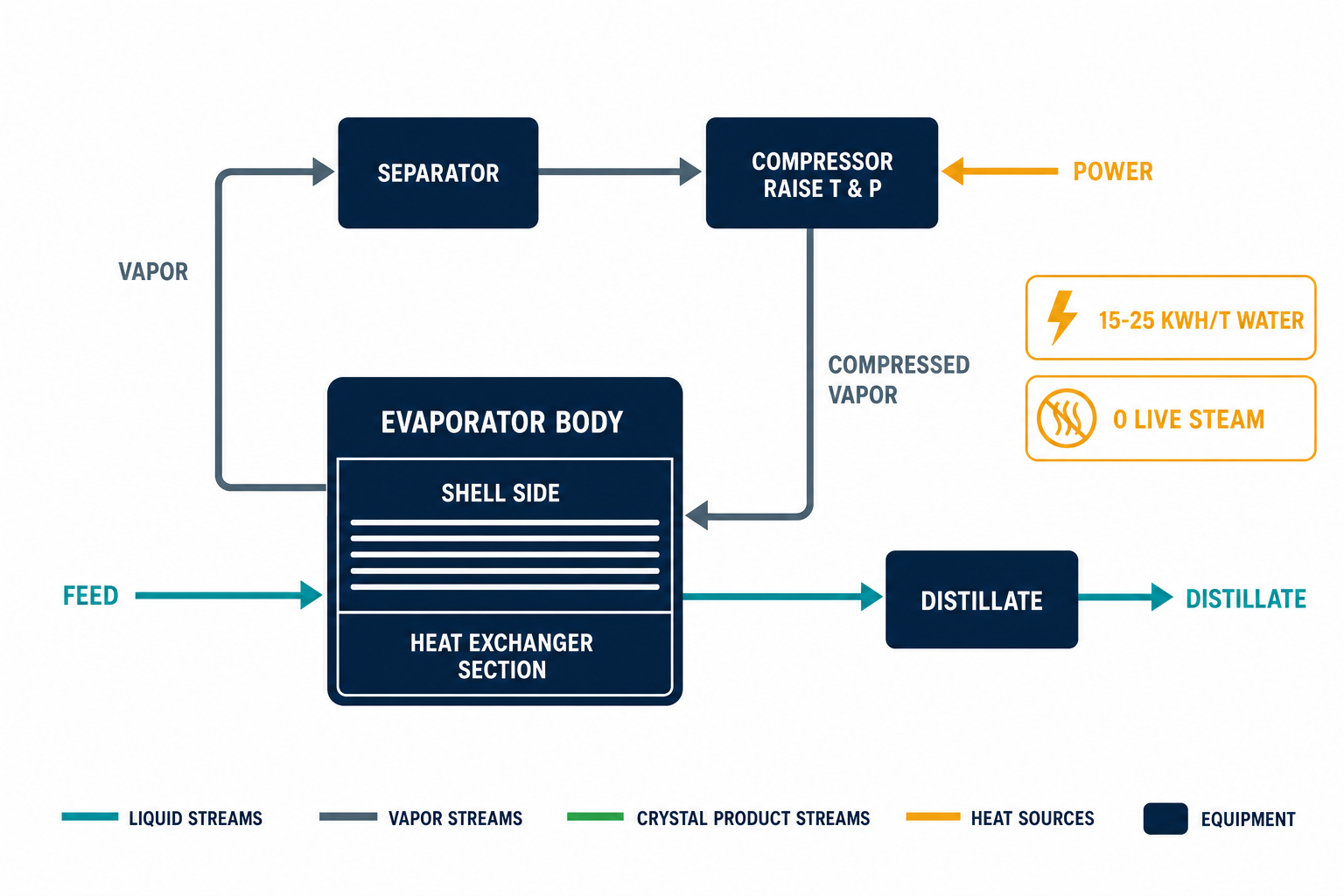
Latent heat is recycled inside a single closed loop: vapor is compressed to a usable condensing temperature, condensed on the same heat-transfer surface that generated it, and the condensed water leaves as clean distillate.

Simplified MVR Flow Diagram

Feed → Heat exchanger (vaporize) → Separator → Compressor (raise T & p) → Shell side (condense) → Distillate out

One compression stage closes the loop — the temperature lift only needs to cover the boiling-point elevation plus the driving ΔT across the heat-transfer surface.

01

Evaporation

Feed liquid boils on the heat-transfer surface — falling film for clean low-viscosity feeds, forced-circulation for scaling or crystallizing service. See process configuration.

02

Vapor–Liquid Separation

The vapor body or separator disengages entrained droplets before the compressor — droplet carry-over erodes impellers and contaminates distillate.

03

Mechanical Recompression

A centrifugal or roots-type compressor raises vapor pressure and saturation temperature so it can condense against the boiling liquid — electrical energy substitutes for live steam.

04

Condensation & Distillate

Compressed vapor condenses on the shell side, releasing its latent heat to the evaporating liquid. Condensate exits as clean distillate, ready for reuse or discharge.

Core Components

What an MVR Train Is Built From

Six modules make up every MVR plant. Some are manufactured in-house; others are integrated from qualified partners — engineering responsibility is never outsourced.

01 · Heart of the Plant

Vapor Compressor

Centrifugal or roots type, sized to the required temperature lift and vapor volume. The compression ratio is limited by compressor type — this is the hard ceiling on how much boiling-point elevation an MVR train can absorb.

75–85%isentropic efficiency, centrifugal type; lower for roots-type
02 · Heat Transfer

Evaporator Body & Heat Exchanger

Falling-film or forced-circulation configuration selected by feed fouling tendency and viscosity — the same Dimension B decision as any evaporator, independent of the MVR energy strategy.

2–3 m/sforced-circulation tube-side velocity; heater temperature rise kept ≤10 °C to prevent wall boiling
03 · Vapor Disengagement

Vapor–Liquid Separator

Custom vapor bodies sized for vapor velocity and entrainment control. A larger body is the standard remedy when droplet carry-over threatens compressor internals or distillate quality.

Clean distillatecondensate recovery as process water — a core benefit in ZLD service
04 · Drive

Motor & Variable Frequency Drive

The VFD controls compressor speed against evaporator duty — part-load turndown without wasting compression work. Motor and VFD efficiency both enter the specific-energy balance.

400 / 690 V3-phase supply at compressor ratings of 200 kW to >2 MW for industrial-scale plants
05 · Vacuum & Non-Condensables

Vacuum System

Liquid-ring pumps or ejectors remove non-condensable gases that would otherwise blanket the heat-transfer surface. Cooling water at 25–32 °C is required for condensation duty.

25–32 °Ccooling-water temperature required for condensation across all energy-reuse routes
06 · Control

Automation & Control

PLC/SCADA loops holding the compression ratio, boiling temperature and feed rate in balance — including density and temperature instrumentation that protect the compressor against surge.

Start-up steamsmall amount of motive steam used only to bring the train to steady state
Specific Energy

What Determines Where in 15–25 kWh/t You Land

Four variables set the number. Two of them come from your feed chemistry — which is why MVR economics must be screened against feed data, not catalog figures.

VariableEffect on Specific EnergyGoverned By
Compressor pressure ratio
Higher compression ratio means more kWh per tonne — but enables a larger ΔT across the heat exchangerBoiling point elevation of the feed sets the minimum lift the compressor must deliver
Boiling point elevationBPE
High dissolved solids (NaCl brine, NaOH solutions) raise BPE, reducing effective ΔT and increasing specific energy demandFeed composition — measured, not assumed. BPE of 2–4 °C with centrifugal compression typically yields 18–22 kWh/t; above 6 °C expect the upper end of the range or consider hybrid MVR + multi-effect
Compressor isentropic efficiency
Every point of efficiency lost appears directly as additional electrical consumption per tonne evaporatedCompressor type: typically 75–85% for centrifugal, lower for roots-type
Motor & VFD efficiency
Electrical losses between the grid and the impeller add to the delivered specific energyDrive selection and part-load profile of the plant

Figures reflect typical industrial ranges observed in operating references; project-specific selection requires heat and mass balance, utility cost modeling (steam vs. electricity) and compressor / boiler availability analysis.

Hybrid Routes

When One Strategy Isn't Enough

MVR, multi-effect and TVR are not mutually exclusive. Hybrids are common when a single strategy cannot meet the energy target within CAPEX constraints.

Documented Hybrid Configurations

MVR combined with — not opposed to — thermal routes

Four hybrid patterns cover most field deployments. Each is selected on project-specific heat and mass balance, not visible from reference tables:

(a) MVR on Effect 1 of an existing multi-effect train  (b) TVR booster on a multi-effect train
(c) MVR pre-concentrator + FC crystallizer back end  (d) Falling-film front + forced-circulation crystallizing end

For high-BPE feeds where MVR alone would push toward the upper end of the energy range, hybrid MVR + multi-effect keeps the compression ratio inside the compressor’s operating envelope. See the ZLD solution line for where pattern (c) is standard practice.

Technical Specifications

MVR System Envelope — Published Supplier Data

Indicative ranges aggregated from published supplier specifications of MVR evaporator and compressor builders. For route screening only — not a process guarantee for any specific project.

System SectionParameterPublished Indicative RangeApplies To / Basis
Whole trainEvaporation capacity0.5–10 t/h standard series · pillow-plate units 10–200 t/h · salt lines 5–500 t/dstandard wastewater series; large-format plate units; modular multi-train salt plants
Whole trainSpecific energy10–40 kWh per t evaporatedpublished spread across configurations: rising-film 15–40 · falling-film 20–45 · forced-circulation 30–60 kWh/t; low-BPE feeds typically screen at the lower end
Whole trainLive steam≈0 after start-up (0–0.3 t/h start-up & standby)all-electric drive once the vapor loop closes
Whole trainTurndown / availability50–100% turndown · ≥95–98% availabilityVFD compressor control; redundant pumps plus planned CIP at intervals ≥10–20 days
Evaporation bodyOperating temperature45–75 °C low-temp vacuum · 70–95 °C high-temp duty · down to 40 °Cthermal-sensitivity window of the feed sets the film temperature
Evaporation bodyShell-side pressure6–25 kPa(abs) typical · 20–80 kPa(abs) design windowvacuum operation, set point load-dependent
CompressorDischarge pressure / ratio45–120 kPa(abs) · ratio 1.2–2.0 (roots ≈1.2–1.6)discharge sets heat-transfer ΔT and capacity; BPE above 15–20 °C points to two-stage compression
CompressorTemperature lift8–20 °C (current industry level)single-stage lift; roots series publishes 75→93–97 °C
Roots seriesFlow / power / MVR duty18–1,050 m³/h · 18.5–1,200 kW · 0.25–15 t/h14-model positive-displacement compressor series
ElectricalPower supply380–480 V LV or 3.3–11 kV MV · 50/60 HzVFD soft-start, load tracking, anti-surge protection
Heat-transfer surfaceSurface comparisonpillow plate 3,500 W/m²·K · shell-and-tube 2,700 · gasketed plate 5,600selection by fouling, pressure and hygiene class
MaterialsWetted partsSS316L standard · duplex 2205/2507 · Ti · Hastelloychloride and corrosion chemistry of the liquor

Ranges aggregate published specifications from MVR system and compressor builders (roots and centrifugal series, wastewater and salt-line configurations). Figures are supplier-published indicative values for screening; a project number requires heat and mass balance on your feed analysis, BPE curve and utility set.

Main Process Modules

The Train, Module by Module

Each module is selected on feed chemistry and duty — the envelope column gives published operating ranges per module type, not a single-project specification.

ModuleEquipment TypesSelection BasisIndicative Operating Envelope
Evaporation bodyFalling-film · forced-circulation · rising-film tubular · pillow-plateheat sensitivity, viscosity, fouling and crystallization tendency of the feedFF 20–45 · FC 30–60 kWh/t; film temperature 40–95 °C
Vapor compressorRoots (positive displacement) · centrifugal turbocapacity and pressure ratio: roots mainly below 2 t/h duty; centrifugal 2–50 t/h and aboveratio 1.2–2.0 · lift 8–20 °C · discharge 45–120 kPa(abs)
Vapor–liquid separatorDemister-equipped separation vesseldroplet carryover control on salt-spray duties; tangential entry minimizes pressure dropboiling is kept in the separator, off the heating surface
Preheater trainPlate / shell-and-tube on condensate and vent heatheat recovery ahead of the evaporation bodycondensate and secondary-vapor heat recovery published as standard
Condenser & vacuum systemSurface condenser · vacuum pumps · NCG handlingvacuum level and non-condensables removalshell-side 6–25 kPa(abs)
CIP & anti-scalantIn-line CIP skid plus chemical dosingfouling-control strategy for the dutyCIP interval ≥10–20 days · continuous runs ≥20 days published
Crystallizer (downstream)DTB · Oslo · FCwhen solids or a salt product must be recoveredNaCl-class purity ≥99.2% in published salt lines
AutomationPLC · HMI · SCADArecipe handling, ΔT protection, anti-surge interlocksavailability ≥95–98% with planned CIP

Module envelopes follow the published supplier data above; the boundary conditions between modules (BPE curve, ΔT split, circulation rate) are project-specific and set at design.

Limitations to Design Around

Compressor maintenance (bearings, seals) is the standing OPEX item; the maximum compression ratio is limited by compressor type; and higher boiling point elevation reduces the MVR benefit. MVR economics are electricity-price sensitive — screen against your utility contract, not against benchmark tariffs. All figures on this page are indicative ranges for preliminary screening, not a process guarantee.

MVR in the Field — Case Studies & Technical Guides

Large evaporation crystallization project under installation
Technology

Evaporation Plant Economics: CAPEX and OPEX

Evaporation plant cost structure explained: CAPEX breakdown, 2026 MVR pricing benchmarks, materials price ladders, OPEX and SEC formulas, payback calculation, hauling economics, rent-vs-buy, and multi-effect-to-MVR retrofit returns.

Read More »
FAQ · Engineering Answers

MVR Questions We Answer Most

Recurring questions from engineers screening an MVR route for the first time.

QThe range says 15–25 kWh per tonne of water. What decides my number?

Four variables: compressor pressure ratio, boiling point elevation of the feed, compressor isentropic efficiency (75–85% centrifugal, lower for roots), and motor / VFD efficiency. For BPE of 2–4 °C with centrifugal compression, expect 18–22 kWh per tonne. For BPE above 6 °C, expect the upper end of the range — or a hybrid MVR + multi-effect configuration.

QWhat utilities does an MVR plant need on site?

Stable electrical capacity at the compressor rating — typically 200 kW to over 2 MW for industrial-scale plants, at 400 V or 690 V 3-phase — plus a small amount of start-up steam and cooling water at 25–32 °C for condensation duty. No live steam is consumed in steady-state operation.

QIs MVR the same thing as a heat pump or a TVR?

No. MVR is mechanical recompression of process vapor by an electrically driven compressor (Dimension A energy strategy). TVR uses high-pressure motive steam through an ejector — no rotating equipment, but a compression ratio ceiling of roughly ≤1.5× per stage and dependence on motive steam at ≥8 bar(g). Vacuum / low-temperature evaporation is a separate operating-temperature choice that can combine with either.

QDoes MVR work on high-TDS or scaling feeds?

Yes — but pair it with the right process configuration. High-TDS brines carry boiling point elevation that eats into the effective ΔT, and scaling feeds need forced-circulation service at 2–3 m/s tube-side velocity with the heater temperature rise held at ≤10 °C. The energy strategy and the heat-transfer configuration are orthogonal decisions; MVR constrains neither.

QWhen is MVR the wrong choice?

When electricity is expensive or unreliable relative to steam, when grid capacity at the compressor rating is unavailable, or when feed boiling point elevation is high enough to push the required compression ratio past the compressor type’s envelope. In those cases multi-effect with a TVR booster — or a hybrid — usually screens better. The comparison page carries the full decision table.

Screening an MVR Route?

Send us feed analysis (including TDS and expected boiling point elevation), throughput and site utility prices. We will return a preliminary MVR vs. multi-effect vs. TVR screening with indicative specific energy — not a brochure.

Request a Proposal

Send your feed characterization (TDS, COD, main salts, viscosity), throughput and product targets — we respond with a preliminary process route within two business days.