Membrane-evaporation hybrid systems pair low-energy membrane concentration (RO, ultra-high-pressure RO, UF, and MBR pretreatment) with a right-sized thermal evaporation and crystallization finish, delivering Minimal Liquid Discharge (MLD): maximum water reuse and brine volume reduction without committing to the full evaporation capacity of Zero Liquid Discharge (ZLD). The engineering logic is simple and economic — membranes remove water at a fraction of the energy cost of boiling, so the evaporator only has to process the final, most concentrated fraction of the brine. Externally reported field results on cooling-tower blowdown have demonstrated up to 70× volume reduction (99% freshwater recovery) by membrane steps alone before any thermal stage is reached. This guide explains how the chain is assembled, where each membrane technology sits, and where physics forces the handover to MVR evaporation.
MLD vs. ZLD: What Each Actually Promises
The two terms are frequently conflated, and the difference is contractual as much as technical:
- MLD (Minimal Liquid Discharge) treats water to the maximum practical reuse level and manages the resulting concentrate — but does not promise total evaporation or crystallization of every liter. A small concentrated brine stream may still leave the site.
- ZLD (Zero Liquid Discharge) commits to no liquid leaving the plant boundary at all: everything is either recovered as water or discharged as dry solids, which mandates thermal evaporation plus crystallization. See the ZLD solutions overview (illustrative application) for the full architecture.
MLD is often the rational first investment: it captures roughly 80–95% of the water-reuse benefit at a materially lower capital and energy cost, and it can be upgraded to ZLD later by adding the thermal finish — sized, critically, to the post-membrane brine flow rather than the raw wastewater flow.
Why Membranes Do the Heavy Lifting
Making water is cheap when you push it through a membrane and expensive when you boil it. The purpose of membrane concentration is therefore to remove the maximum possible volume of water before the brine ever reaches the evaporator — substituting for evaporation capacity, trucked disposal, or deep-well injection, all of which are more expensive per cubic meter.
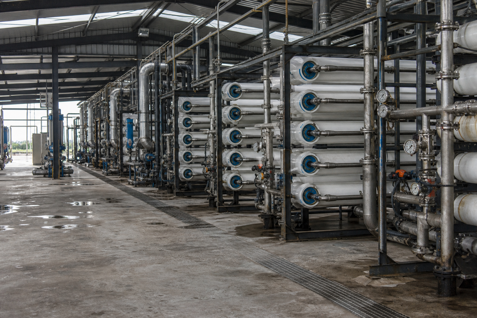
The volume-reduction ladder from an externally reported pilot campaign on cooling-tower blowdown (feed approximately 1,800 mg/L TDS) illustrates the stepping:
| Volume reduction | Water recovery | Concentrate volume (from 100 m³ feed) | System implication |
|---|---|---|---|
| 5× | 80% | 20 m³ | Conventional RO alone |
| 10× | 90% | 10 m³ | RO + partial softening |
| 20× | 95% | 5 m³ | Softening + high-recovery RO |
| 40× | 97.5% | 2.5 m³ | Chemical softening + UHP RO |
| 70× | 99% | ~1.4 m³ | Robotic softening + UHP RO stage |
Every step up the ladder increases plant complexity and investment — which is precisely the trade an MLD design must optimize. Recovery targets should be set by lifecycle cost, not by records.
The Membrane Toolbox, Up the Concentration Curve
MBR: biological pretreatment for organic-bearing wastewater
When the stream carries COD, ammonia, or variable organics, a membrane bioreactor precedes desalination. The membrane replaces the secondary clarifier, which shrinks footprint substantially and enables modular, containerized installations. Selection criteria that actually determine lifecycle performance: matched-to-water-quality design (COD/BOD, ammonia, TSS, flow variability); membrane material — PVDF hollow fiber or plate sheet, with flux stability and backwash cycle setting cleaning frequency; automated CIP capability; PLC/SCADA automation that reduces dependence on operator skill; and total cost of ownership (membrane replacement cycle, aeration energy, maintenance labor) rather than purchase price.
Ultrafiltration (UF): the bodyguard for RO
UF membranes with 0.01 μm pore size reject suspended solids, bacteria, and colloids while passing dissolved minerals — they do not desalinate, and that is the point. Positioned ahead of RO, UF lowers the silt load and stabilizes RO feed quality; automatic backwashing keeps flux stable. In potable contexts UF retains beneficial minerals; in industrial MLD chains its job is protecting the downstream RO from fouling.
Reverse osmosis: the workhorse
RO applies pressure across a semi-permeable membrane to reject ions, heavy metals, and microbiology at up to 99% rejection in multi-pass arrangements. Standard multi-stage configurations chain prefiltration (sediment), carbon (chlorine removal), the RO membranes, and post-treatment. A side benefit worth engineering for: RO also rejects Ca and Mg, softening the water that later reaches evaporator feed — membranes as corrosion and scale protection for thermal plant.
Ultra-high-pressure RO: pushing toward 130,000 mg/L
Conventional RO stalls far below the concentrations MLD aims for. Ultra-high-pressure RO systems using spiral-wound membranes rated at 1,800 psi (120 bar) can concentrate brine up to roughly 130,000 mg/L TDS while managing scaling and fouling — roughly four times seawater salinity. This stage is what makes deep volume reduction feasible without thermal energy.
Chemical softening: the enabler nobody skips
High recovery fails without removing the ions that scale membranes first. Modern practice uses automated chemical softening — systems with real-time calcium sensors and managed precipitation that adapt to fluctuating water chemistry. The lesson from operating plants is unambiguous: the prerequisite for high-recovery RO is removing scale-forming ions before the membranes, not after they foul.
Where Membranes Stop: The Osmotic Pressure Limit
The handover point from membrane to evaporator is not a design preference — it is physics. Osmotic pressure rises with salt concentration (per the van’t Hoff relation, π = iCRT), so every liter of water removed from brine makes the next liter more expensive to push through a membrane:
- Seawater (~35,000 mg/L TDS) exerts roughly 27 bar of osmotic pressure — comfortably within standard RO;
- At 75,000 mg/L the osmotic pressure approaches 60 bar, consuming most of a conventional RO’s margin;
- Near 130,000 mg/L, osmotic pressure exceeds 100 bar, demanding the full 120 bar of UHP RO with diminishing net driving force.
Beyond that, no practical membrane pressure can win: thermal evaporation takes over, its economics unaffected by salinity-driven osmotic pressure (though boiling-point elevation and viscosity must be engineered for — the matching criteria are covered in the evaporator selection guide).
The Complete Hybrid Chain
A full membrane-evaporation MLD/ZLD train is assembled in this order, with typical salinity progression:
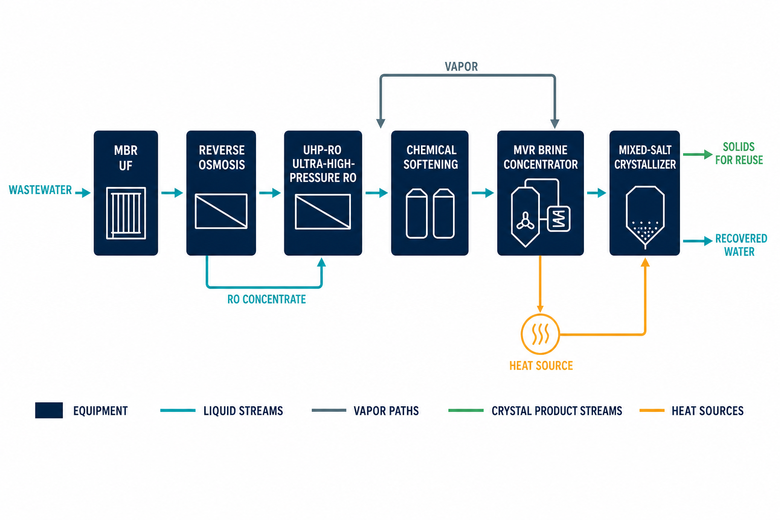
- Biological treatment (MBR) — degrades organics, removes nitrogen; TDS essentially unchanged;
- Softening + filtration/UF — removes Ca/Mg/silica and suspended solids; protects everything downstream;
- RO — first major water recovery (typically to 5–10× volume reduction); permeate recycled;
- UHP RO — pushes concentrate toward 100,000+ mg/L TDS where feed chemistry allows;
- MVR evaporator — concentrates the final membrane reject to near-saturation slurry;
- Crystallizer / salt separation — precipitates mixed salt or fractions it into usable products.
The defining economic feature: the thermal stages at the end are sized to the small, concentrated flow exiting the membranes — not to the raw plant effluent. Right-sizing the evaporator this way is where the hybrid architecture earns its return; conversely, skipping the membrane stages forces the evaporator to evaporate water that membranes could have removed at a fraction of the energy.
Choosing the Route by Feed Salinity
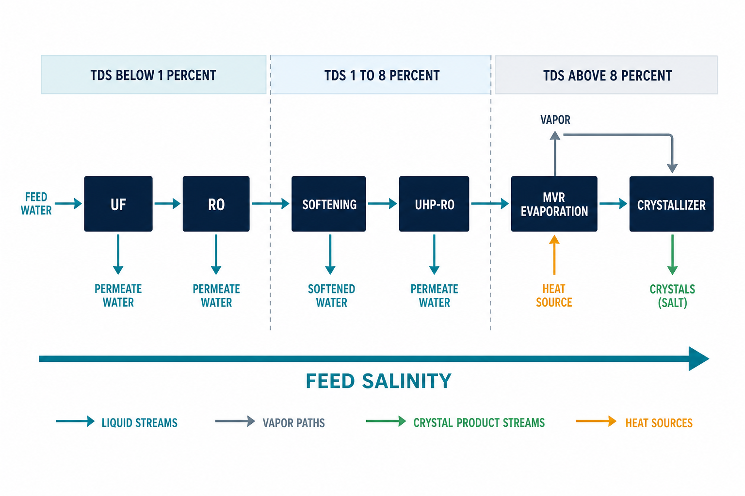
| Feed TDS | Recommended architecture | Rationale |
|---|---|---|
| <10,000 mg/L | Biological/UF + RO; permeate reuse directly | Membranes alone hit high recovery; no thermal stage needed |
| 10,000–50,000 mg/L | Softening + RO + UHP RO; small MVR finish for the reject | Membranes still economic for bulk water removal; thermal polish only |
| >50,000 mg/L (or high scaling tendency) | Direct thermal: MVR evaporation + crystallization | Osmotic pressure erodes membrane economics; thermal handles salinity without that penalty |
Bordered cases — high silica, high organics, rapidly variable chemistry — shift the boundaries toward earlier thermal handover, which is why feed characterization precedes every MLD design.
Operating a Hybrid Plant: What Determines Availability
Design gets a hybrid plant built; operations discipline determines whether it still meets recovery targets two years later. The recurring themes from operating installations:
- Scaling control is continuous, not episodic. Softening performance should be monitored with online hardness or calcium sensors, with antiscalant dosing adjusted to the measured trend rather than a fixed recipe — feed chemistry drifts, and yesterday’s dose becomes today’s fouled element.
- CIP strategy sets membrane life. Cleaning frequency is dictated by normalized flux decline, not calendar. Waiting too long allows irreversible fouling; cleaning too aggressively or too often shortens element life. A disciplined baseline of normalized permeate flow, differential pressure, and salt rejection is what makes that judgment data-driven.
- Instrumentation carries the plant. Conductivity (permeate and concentrate), pressure per stage, and flow are the minimum telemetry; without them, recovery creep goes unnoticed until scaling announces itself.
- Respect the evaporator interface. The membrane reject entering the thermal stage is concentrated, scale-prone, and often foaming. Boiling-point elevation and viscosity at the handover salinity must be inside the evaporator’s design envelope — a mismatch here shows up as reduced heat transfer and shortened cleaning intervals, which the evaporator type comparison covers in selecting the right crystallization-compatible configuration.
Where These Systems Earn Their Keep
MLD hybrids are deployed where water is scarce, discharge permits are tightening, or brine disposal costs are escalating: cooling-tower blowdown at power and data-center sites (the pilot case above), mining and oil-and-gas produced water, semiconductor and pharmaceutical plants requiring high-purity reuse water, and chemical complexes with multiple mixed-effluent sources. Common drivers across all of them: complex wastewater with discharge limits that conventional treatment cannot meet, and a water price or disposal cost that makes each recovered cubic meter valuable.
Process Modules and Candidate Equipment
| Process Module | Candidate Equipment | Selection Basis |
|---|---|---|
| Biological pretreatment (when organics present) | MBR membrane bioreactor | Degradable COD before membranes; MBR pairs biology and UF in one step |
| Softening + filtration | Lime/soda-ash softener + UF | Ca, Mg, and silica suppression; the enabler for high-recovery RO |
| Primary membrane concentration | Brackish/sea-water RO trains, 70-85 bar class | Lowest energy per cubic meter recovered; limited by osmotic pressure |
| High-pressure polishing membrane | Ultra-high-pressure RO, 100-120 bar class | Extends membrane range toward ~130,000 mg/L reject; judged on flux and scaling control |
| Thermal finish | MVR evaporator (forced-circulation or falling-film) | Handles the membrane-reject fraction; compressor energy vs. steam price decides the size |
| Salt production / disposal finish | Evaporation crystallization and salt separation | Needed only when solids or segregated salts are the endpoint, not just volume reduction |
When This Route May Not Fit
A membrane-led hybrid is not always the honest recommendation. It may not fit when: the stream is dilute and high-flow (a few hundred to a few thousand mg/L) with no tightening discharge limit, where a conventional treatment train or RO alone is sufficient and the thermal finish would sit idle; pretreatment cannot realistically control the foulants, for example silica near or above its solubility ceiling or refractory organics that no softening chemistry removes economically, so membranes would foul faster than they concentrate; the scale is small and the UHP-RO package plus its pretreatment carry no economy, leaving a simple thermal unit cheaper to build and simpler to run; or the water chemistry swings widely shift-to-shift, so the softening and membrane stages never see a stable feed and availability collapses. In those cases a direct thermal route, or deferral of the whole project, serves better than forcing the chain.
What Must Be Verified
Before committing to an MLD chain, verify with data rather than assumptions: a full water characterization of the actual feed, including silica, barium, strontium, and organics, not just TDS and chlorides; scaling-tendency modeling or bench tests at the projected recoveries, so the softening duty is sized on measured ion chemistry; membrane pilot data or referenced analog-project performance at comparable salinity and fouling load; at the membrane-to-thermal handover point, the boiling-point elevation and viscosity of the reject brine, which size the evaporator and set its heat-transfer penalty; the site’s real electricity versus steam prices, which decide how much of the water the membranes should take before the MVR finish; and a confirmed disposal or outlet route for the final concentrate or salts, because the whole chain is sized around where that stream is allowed to go. Figures quoted on this page are supplier-published and externally reported ranges, not a project guarantee.
FAQ
What is the difference between MLD and ZLD?
MLD maximizes water recovery and minimizes brine volume but does not promise zero liquid discharge — a small concentrate stream may still leave site. ZLD commits to no liquid discharge at all, which requires full thermal evaporation and crystallization. MLD captures most of the water-reuse value at lower cost and can be upgraded to ZLD by adding a right-sized thermal finish.
How concentrated can RO get brine before evaporation is needed?
Conventional RO is practical to roughly 70,000–80,000 mg/L TDS; ultra-high-pressure RO operating at 1,800 psi (120 bar) extends this to approximately 130,000 mg/L. Beyond that, osmotic pressure exceeds 100 bar and thermal evaporation becomes the more economic route.
Why does high-recovery RO need chemical softening first?
Calcium, magnesium, and silica concentrate along with the salt and precipitate on membranes as recovery rises, fouling and scaling the elements. Automated chemical softening with real-time calcium monitoring removes these ions before the membranes, which is what makes 95–99% recovery operationally sustainable.
Is a hybrid system cheaper than evaporation alone?
For low- and moderate-salinity feeds, yes — membranes remove the bulk of the water at lower specific energy, so the evaporator is sized to only the final concentrated fraction, cutting both CAPEX and operating cost. For very high-salinity feeds (>50,000 mg/L TDS), membrane economics degrade and direct thermal treatment is usually cheaper.
What brine volume reduction is realistic with membranes only?
Externally reported pilot results on cooling-tower blowdown demonstrate a ladder from 5× (80% recovery) with conventional RO up to 70× (99% recovery) with softened UHP RO. Each step adds complexity and cost, so the optimal point depends on energy prices, disposal costs, and water value at the specific site.