Crystallizing vitamin C (ascorbic acid) from concentrated fermentation-purification liquor is a crystal-size and stability problem: the product oxidizes in the presence of heat, air and alkali, and careless supersaturation control fills the crystallizer with fines. The configuration that answers both is a two-stage continuous cooling crystallization train – stage one vacuum-flash DTB crystallization at around 30°C, stage two cooled Oslo fluidized-bed crystallization down toward 0°C – designed for a 7 t/h feed of 50°C VC concentrate. The reference is a supplier-published process description for a Hebei pharmaceutical producer – an external industry reference, not an EvapCryst delivery.
Why Vitamin C Demands a Cooling Crystallization Route
Ascorbic acid’s properties set the design boundaries. It is water-soluble, stable in acidic conditions, and progressively destroyed by oxygen, heat, light and alkaline exposure – so every added degree of process temperature and every hour of hold time is a yield loss vector. Its solubility in water rises meaningfully with temperature, which makes cooling – not evaporation – the natural supersaturation generator: you make crystals by removing sensible heat, not by boiling the product liquor. The reference feed arrives at 50°C from the upstream concentration step, and the train cools it in two controlled steps to near 0°C, harvesting the dissolved VC as it exits solution.
The second boundary is crystal quality. Supersaturation is the driving force of crystallization, but driven past the metastable limit it spawns nuclei instead of growing existing crystals – a crystallizer full of fines that filter badly, wash poorly and dust in handling. Continuous crystallization manages this by holding the liquor continuously inside the metastable zone while crystal surface area, provided by a suspended seed bed, absorbs the supersaturation as growth.
Illustrative Feed Envelope
| Parameter | Illustrative range | Basis / note |
|---|---|---|
| Feed | Vitamin C concentrated liquor (purified fermentation product) | From upstream evaporation/concentration |
| Feed rate | 4-10 t/h class | Reference: 7 t/h |
| Feed temperature | 45-60°C | Reference: 50°C |
| Stage 1 (vacuum flash) | ~30°C adiabatic flash cooling | Reference setpoint |
| Stage 2 (cooled Oslo) | Cooled toward 0-5°C | Reference: 0°C control point |
| Product targets | Coarse, free-flowing VC crystals; high yield from mother liquor | Downstream: thickening, centrifugation, drying |
An illustrative envelope from the supplier-published process values plus screening ranges for purified fermentation liquors – not a customer dataset, not an industry average, not a project guarantee.
Process Solution: Two Stages, Two Crystallizer Physics

Stage one is a vacuum-flash DTB (draft-tube baffle) crystallizer controlled near 30°C. Hot feed enters the vessel bottom and mixes with the circulating crystal slurry; the mixed liquor rises through the draft tube driven by a low-speed propeller, reaches the boiling surface where a small adiabatic flash removes both water vapor and sensible heat, and returns supersaturated liquor down through the suspended crystal bed. Two DTB features earn their place in VC duty. The fines-destruction circuit: a draw-off of liquor carrying excess micro-crystals passes through a heating dissolution loop – warming the liquor just enough to redissolve fines – and returns to the vessel, converting would-be fines into growth capacity on the surviving crystals. And the low-speed bottom-mounted propeller: compared with high-shear external circulation, gentle internal circulation generates far fewer new nuclei, which is precisely what coarse product requires.
Stage two is a cooled Oslo (fluidized-bed) crystallizer controlled toward 0°C. Liquor from stage one passes through an external heat exchanger that removes both the incoming sensible heat and the heat of crystallization; the cooled, supersaturated liquor flows up through a classified fluidized bed where crystals grow in size-graded suspension, and the largest crystals harvest at the bottom while the finest remain entrained for further growth. The Oslo’s fluidized-bed geometry is the classic choice when the objective is large, uniform crystals from a cooling duty.
The train closes with a thickener after stage two – desupersaturating the final slurry so remaining growth happens in the thickener rather than in downstream piping, raising yield and enlarging crystal size ahead of centrifugation – then centrifugation and drying under conditions that respect VC’s oxidation sensitivity. Clean-in-place provisions run through the design: the reference describes three-dimensional spray heads at the flash-vessel top for washing crystal crusts off the walls, tangential feed inlets on each stage flushable with mother liquor or process water, and the fines loop doubling as a dissolution circuit.
Technical Features
Four features define this train. Metastable-zone discipline across two stages: splitting the cooling duty (30°C flash, then to 0°C in the Oslo) keeps each stage’s supersaturation generation inside the metastable zone instead of asking one vessel to absorb the whole 50°C span. Fines destruction: the dissolution loop is the mechanism that converts an over-nucleated slurry back into growth capacity – it is what raises average crystal size without raising residence time. Classified growth in the Oslo bed: the fluidized bed separates growth zones by crystal size, letting large crystals grow larger while fines recirculate. And CIP engineering built in from the start: crystal service fouls walls and inlets by nature; a crystallizer that cannot be cleaned in place loses availability month by month.
Process Modules
| Process module | Candidate equipment types | Selection rationale | Module duty |
|---|---|---|---|
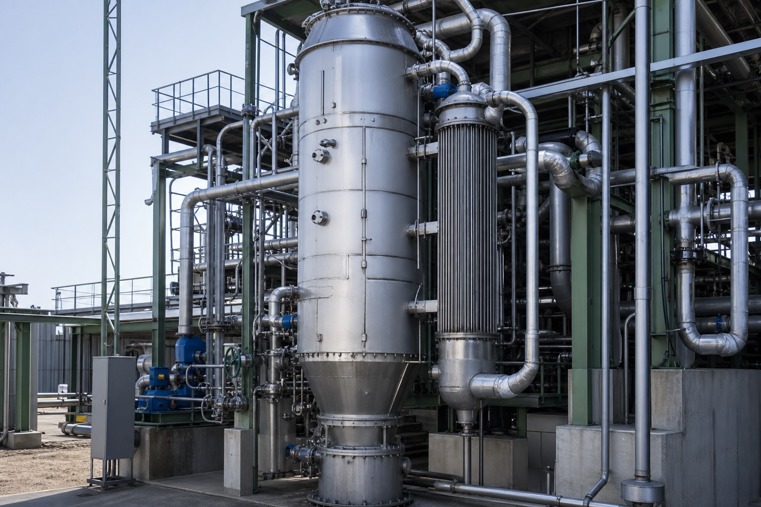
| Stage 1 crystallizer | Vacuum-flash DTB with draft tube, low-speed propeller | Adiabatic cooling without heat-exchange surface; gentle internal circulation | First-stage cooling and seed growth at ~30°C |
| Fines management | Fines draw-off + heating dissolution loop | Redissolves micro-crystals; redirects growth to product crystals | Crystal size distribution control |
| Stage 2 crystallizer | Cooled Oslo fluidized-bed with external heat exchanger | Classified bed grows large uniform crystals at deep cooling | Final-stage yield at 0-5°C |
| Cooling utility | Chilled water / brine circuit to stage-2 exchanger | Deep cooling duty below ambient | Heat removal for crystallization |
| Desupersaturation | Thickener after stage 2 | Finishes growth; protects downstream piping | Yield and crystal size before dewatering |
| Dewatering and drying | Centrifuge + low-temperature dryer | Minimal thermal/oxidative exposure | Finished VC crystals |
| Cleaning | 3D spray heads + tangential flush inlets | Crystal crust management without extended downtime | Availability |
Configuration, materials and operating envelopes above are potential considerations only; actual selections depend on liquor composition, crystal specification, cooling utility conditions and plant capacity.
Expected Performance and Limits
The reference describes stable operation with the design’s stated objectives – higher yield, less mother liquor, better product quality and higher automation versus batch crystallization, at the 7 t/h feed scale (supplier-published process description, indicative, not a project guarantee). Engineering-estimate expectations for trains of this class: the majority of dissolved VC exiting solution at the 0°C endpoint depends on the actual solubility curve of your liquor – the residual mother liquor retains VC at its cold solubility, and mother-liquor recycle or rework is where the last yield points live. The honest limits: the route assumes an already-purified, acidic liquor (impurity load shifts metastable behavior and product purity); deep cooling toward 0°C demands chilled utility and careful exchanger design (VC liquors can foul cold surfaces); and oxidation control – deaeration, materials, hold-time discipline – is a process-wide obligation, not a crystallizer feature.

Industry References and Validation
Anchor: a supplier’s published process description of a two-stage continuous cooling crystallization design for a Hebei pharmaceutical producer – vacuum-flash DTB at 30°C plus cooled Oslo at 0°C, 7 t/h feed at 50°C, with fines-destruction, CIP and thickening provisions. External industry reference, not an EvapCryst delivery; it documents design intent and configuration, not measured performance. Validation for your liquor should establish: the actual solubility-and-metastable-zone behavior of your concentrate (these are liquor-specific and decide stage temperatures); an impurity audit (what else crystallizes or inhibits growth); fouling trials on the cooling exchanger at your endpoint temperature; oxidation-loss measurement across a simulated residence time; and crystal-size distribution targets agreed with the downstream separation and drying steps before vessel sizing begins.
Frequently Asked Questions
Why cooling crystallization instead of evaporative?
VC degrades with heat and its solubility falls steeply with temperature. Cooling crystallization generates supersaturation by removing sensible heat at low temperature, never boiling the product – the gentle route the chemistry demands.
Why two stages instead of one?
Spanning 50°C to 0°C in a single vessel would push supersaturation past the metastable zone somewhere in the middle and blanket the bed with fines. Two stages, each inside its metastable window, grow coarse crystals through the whole range.
What does the fines-destruction loop actually do?
It draws off liquor carrying excess micro-crystals, gently warms it to redissolve them, and returns it to the vessel. The dissolved VC then grows on the surviving larger crystals – converting a fines problem into a size advantage.
Why an Oslo for the second stage?
The Oslo’s fluidized bed classifies crystals by size: coarse product harvests at the bottom while fines stay suspended for more growth. For deep-cooling duties where large uniform crystals are the specification, it is the classical geometry.
What is the main operational risk?
Fouling of the stage-2 cooling surfaces and crystal crust formation on vessel walls – both managed by exchanger velocity design and the built-in CIP provisions. The second risk is oxidation from air ingress, which is a sealing and nitrogen-discipline question across the whole train.
When This Route May Not Fit
Batch-production plants with modest tonnages may prefer a simpler stirred-cooled batch crystallizer and accept the size and automation penalty. Liquors with high impurity or color loads may need a purification step before any crystallization strategy works. If chilled utility to near 0°C is unavailable or expensive at your site, the second-stage design changes fundamentally and the economics deserve a re-examination. And if your product specification accepts smaller crystals, the fines-destruction and Oslo investment buys more size than you are paid for.
What Must Be Verified Before Committing
Your liquor’s solubility curve and metastable-zone width across 50°C to 0°C; impurity and color audit with their crystallization behavior; cooling-utility availability and temperature floor; exchanger fouling tests at endpoint; oxidation-sensitivity measurement across residence time; crystal-size specification agreement with solid-liquid separation and drying; and a CIP validation protocol for crystal service.