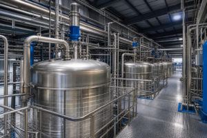
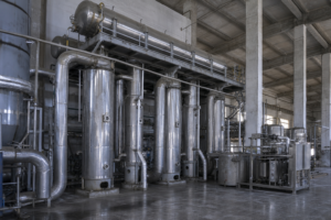
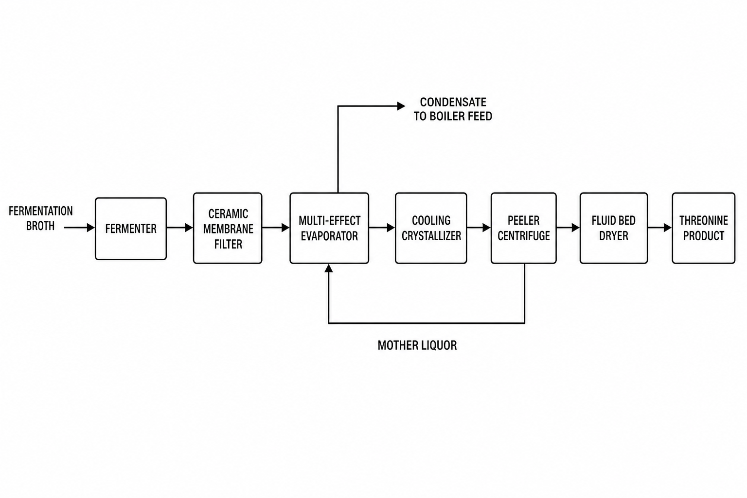
Threonine fermentation broth is concentrated into saleable crystalline product in one downstream train: sterilization, ceramic membrane clarification, multi-effect or MVR evaporation crystallization, two-stage centrifugal separation, and fluidized bed drying. An illustrative feed envelope: the evaporator receives clarified dialysate at roughly 12–13 g/100 mL threonine and discharges crystal slurry at a 58–60% solid-liquid ratio, with condensate clean enough for fermentation make-up water. This page covers section design, the multi-effect versus MVR energy trade-off, and what published plant sizes say about scaling.
Why Threonine Downstream Processing Deserves Its Own Design
Threonine is an essential amino acid produced industrially by aerobic fermentation using genetically engineered Escherichia coli strains. It is the second limiting amino acid in pig feed and the third limiting amino acid in poultry feed, which is why demand concentrates in large feed-grade plants — and why threonine projects are typically specified in tens of thousands of tonnes per year rather than in fine-chemical batches.
The raw broth arriving at separation carries bacteria, residual sugars, pigments, colloids and other by-products alongside the threonine; before fermentation the broth is sterilized at 65–75 °C, after fermentation it flows directly to filtration. Three properties of this broth drive the evaporator design:
- High organic impurity load: everything that is not removed upstream ends up fouling heat-transfer surfaces or contaminating the mother liquor.
- Heat sensitivity of the product: prolonged high-temperature residence degrades color and purity, favoring short-residence evaporator types and modest operating temperatures.
- Crystal quality requirements: feed-grade threonine is sold on uniform particle size, so the crystallizer must grow crystals rather than flash them.
The Complete Process Chain: From Broth to Crystal
Producers such as the Hongmao engineering group publish a consistent process sequence for threonine lines, and the same logic applies whether the plant is sized for 10,000 or 80,000 tonnes per year:
| Step | Function | Key design parameter |
|---|---|---|
| Air pretreatment | Deliver sterile, dry air to the aerobic fermenters (intake above 25 m, away from cooling towers and dust sources) | Air quality for oxygen-consuming fermentation |
| Strain culture | Slope culture → seed culture → final fermentation, restoring strain vitality before inoculation | Three-stage expansion |
| Fermentation | Threonine accumulation by engineered E. coli | Sterilization at 65–75 °C |
| Ceramic membrane filtration | Remove cells and colloids; dialysis water recovers threonine from the concentrate | Retentate becomes bacterial protein for feed |
| Evaporation crystallization | Concentrate the dialysate and crystallize threonine | Feed 12–13 g/100 mL; slurry 58–60% solids (illustrative) |
| Centrifugal separation | Two-stage pusher centrifuge dewaters the crystal slurry | Mother liquor recycled to storage |
| Fluidized bed drying | Remove crystal surface moisture with hot and draught air | Multi-stage screening for uniform granulometry |
Ceramic Membrane Pretreatment Protects the Evaporator
The cheapest place to remove impurities is before the evaporator, not inside it. In the reference process the broth is concentrated and filtered through ceramic membranes, with dialysis water washing threonine out of the concentrate so filtration losses stay low; species above the membrane cut-off — whole cells, debris, colloids — are retained and routed as bacterial protein, a saleable feed ingredient rather than waste.
Only the clear dialysate moves forward to evaporation. This split matters for evaporator economics in two ways. First, clean liquor means slower fouling, longer runs between clean-in-place (CIP) cycles, and a stable overall heat-transfer coefficient. Second, it keeps the threonine crystallization section working on a relatively narrow composition window, which is what makes a 58–60% discharge slurry achievable at consistent crystal size.
Evaporation and Crystallization: Multi-Effect Baseline, MVR Retrofit
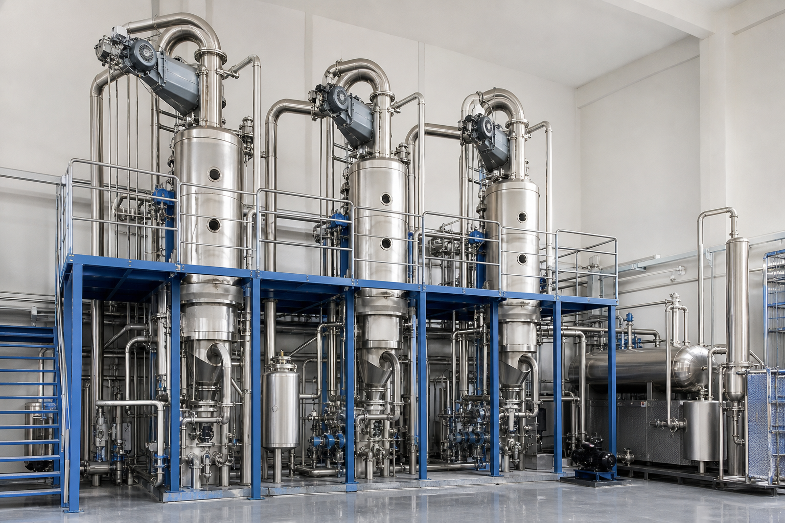
The published reference plants use multi-effect evaporation crystallizers, and this remains the sensible baseline where live steam is cheap and electricity is expensive. The dialysate enters at 12–13 g/100 mL and is concentrated until the discharged slurry reaches a 58–60% solid-liquid ratio, at which point it is ready for the centrifuges.
| Process module | Equipment candidates | Selection basis | Indicative envelope |
|---|---|---|---|
| Clarification | Ceramic membranes, diafiltration | Cell and colloid removal, product recovery | Dialysate ~12–13 g/100 mL |
| Evaporation crystallization | MEE or MVR crystallizer; OSLO / draft-tube | Growth of uniform crystals | Slurry 58–60% solids |
| Dewatering and drying | Two-stage pusher centrifuge; fluid-bed dryer | Residual moisture, granulometry | Feed-grade crystal product |
| Mother-liquor recycle | Recycle tank, controlled purge | Yield, impurity ceiling | Purge to protein feed |
Configuration, materials and envelopes depend on the actual dialysate analysis, product specification, utilities and capacity.
For new builds and energy retrofits, mechanical vapor recompression (MVR) is increasingly the comparison point. An MVR crystallization train compresses its own secondary vapor and reuses it as the heating medium, cutting live steam consumption almost entirely after start-up. Vendors of MVR systems typically quote 20–35 kWh of electricity per tonne of evaporated water, energy savings of 70–90% versus a single-effect evaporator and 50–80% versus thermal vapor recompression (TVR) — supplier-published indicative ranges, not project guarantees. Whether those numbers hold for a specific threonine broth depends on the boiling point rise of the liquor and the reliability of the local power supply — the same engineering checks covered in our MVR evaporation systems overview.
Crystallizer selection follows the product rather than the energy source. Threonine is grown from clarified, relatively low-viscosity liquor, which suits evaporative crystallizers with controlled circulation (OSLO-type growth vessels or draft-tube designs) where crystals spend time in a fluidized bed and grow round and uniform. High-viscosity, fouling-prone duties would instead push the design toward forced circulation — the trade-offs are compared in our forced circulation evaporator guide.
Centrifugal Separation and Fluidized Bed Drying
After crystallization the slurry is distributed to a two-stage pusher centrifuge. The liquid phase leaves with the mother liquor to a collection tank; the crystals deposit on the screen as a filter cake, are pushed from the first to the second drum stage, and exit with very low residual moisture under higher centrifugal force. Mother liquor is not waste: it carries recoverable threonine and is recycled through the evaporator until impurity build-up justifies a purge, often into the protein feed stream.
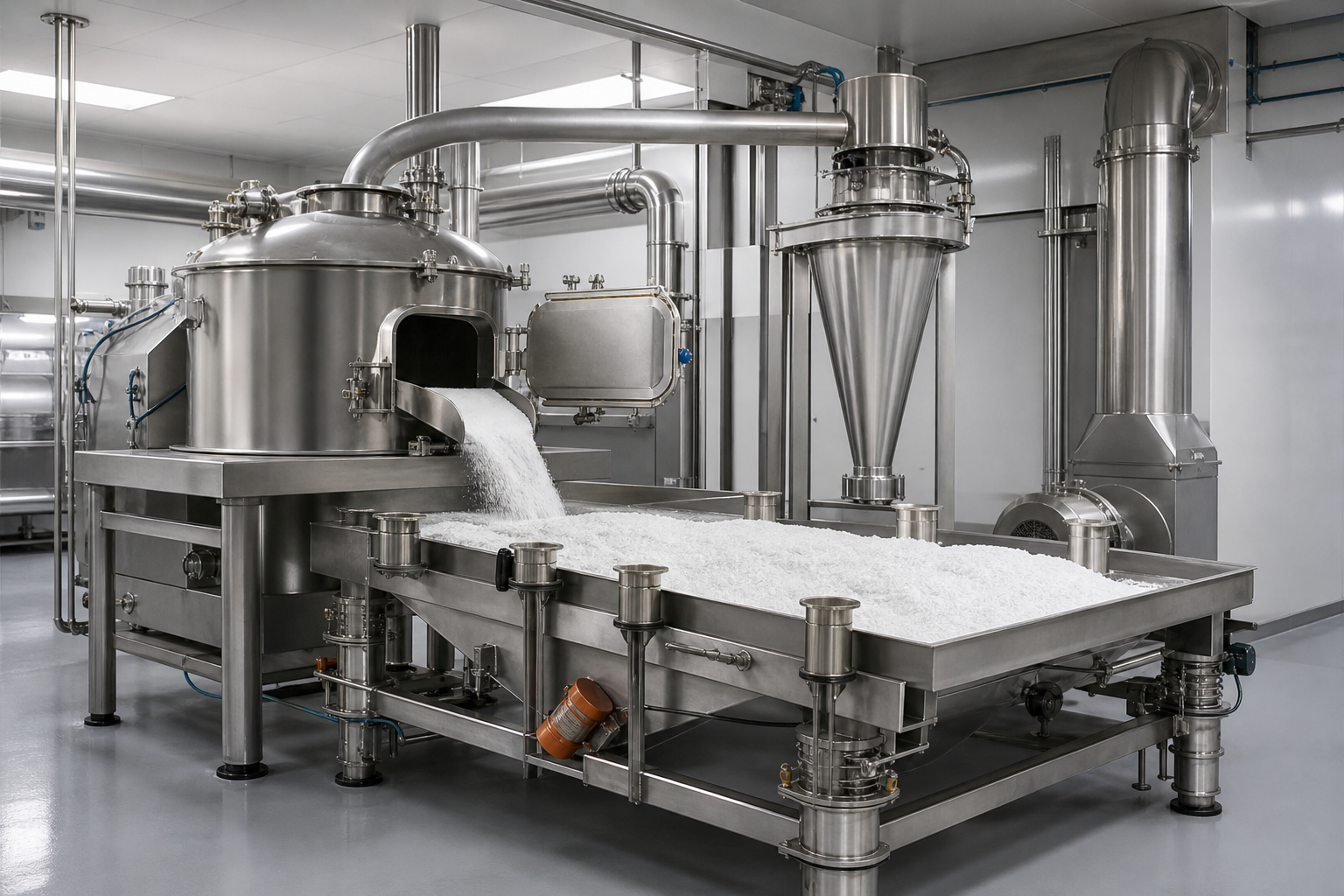
Wet crystals pass over a vibrating screen into a fluidized bed dryer, where hot blast and draught air remove surface and crystal water. Multi-stage screening after drying delivers the uniform particle distribution that feed and food customers specify. Because drying is the last quality gate, the dryer is usually matched to the crystallizer discharge rate rather than oversized, keeping residence time — and thermal stress on the product — short. Drying and packing integration is covered separately in our drying and packing capability page.
Condensate and Energy Recovery Loop
Two water loops close the energy balance of a well-designed plant:
- Evaporator condensate from clean dialysate vapor is collected and reused for fermentation broth blending, cutting fresh water demand.
- Steam condensate from the heating side is returned to the power plant or boiler house, preserving sensible heat.
These small loops carry large operating consequences: a plant evaporating tens of tonnes of water per hour either recovers it as process-grade condensate or pays twice — effluent charges plus fresh water treatment. When MVR replaces part of the steam system, condensate value stays while fuel demand drops, which is why amino-acid retrofit evaluations pair energy with the water balance.
Mother Liquor Management and Overall Yield
Threonine recovery is decided in the mother liquor loop. Centrifuge mother liquor still carries dissolved threonine plus accumulated impurities, so it is recycled to the evaporator feed rather than drained; each pass raises impurity concentration, and when color bodies and salts threaten crystal quality, a controlled purge is taken. The purge still holds protein and amino-acid value, so it is blended into the bacterial protein stream and sold as feed — the co-product logic used across amino acid plants.
Two design habits keep the loop healthy. First, dialysis water quantity on the ceramic membranes is balanced against threonine loss in the retentate: too little water leaves product in the feed stream, too much dilutes the evaporator. Second, the purge rate is set from crystal quality data rather than a fixed schedule, which maximizes threonine yield per tonne of sugar fermented while protecting the product specification.
Reference Plant Sizes
External industry references — published project announcements from engineering groups, not EvapCryst project data — give a sense of how the section scales. One published case: a domestic 80,000 tpy threonine project with a 10 tph evaporative crystallization system, low energy consumption and automatic control as stated targets; another, a dedicated evaporator system for a 70,000 tpy project. At the site level, threonine capacity is often embedded in larger corn deep-processing complexes — one 1,500,000 tpy corn input project produces threonine, tryptophan, and other amino acids side by side — which means the evaporation section is frequently designed to share utilities with starch and glucose lines.
For comparison, the same engineering groups deliver lysine, MSG, and citric acid finishing trains in similar process families; the shared design logic is summarized in our fermentation evaporation and crystallization overview. The tryptophan equivalent of this page — where chromatographic purification and deamination sit upstream of the evaporator — is covered in our tryptophan fermentation broth solution.
When This Route May Not Fit
This route is built for fermentation-derived, feed-scale threonine. It may not fit for extraction- or enzymatic-route threonine, which never produces this broth. It may not fit for small-batch pharmaceutical-grade production, where the train economics assume tens of thousands of tonnes per year and fine-chemical batch crystallization is the right scale. It may not fit where the broth would be sent to evaporation without upstream clarification — cells, colloids and pigments would foul heat surfaces and poison the mother-liquor loop within weeks. And the MVR version of the route may not fit where electricity is expensive or unreliable while low-cost live steam exists: there the multi-effect baseline remains the honest answer, not a compromise.
What Must Be Verified
Before the route is fixed, the validation focus is: a full dialysate analysis — threonine tenor, residual sugars, ash, color bodies, and the boiling point rise of the actual liquor, which sizes the temperature stages. Then the fouling assumption: CIP cycle expectations grounded in the real impurity load, not in clean-liquor catalog values. Then the crystal specification — particle size distribution and purity the feed customer actually enforces — since it selects the crystallizer type. Then site utilities: steam versus electricity prices decide multi-effect versus MVR. Then the mother-liquor purge rate, set from impurity build-up data. Verified dialysate data and, ideally, a bench crystallization run are the evidence base.
Required inputs: the clarified dialysate analysis, plant capacity and product specification, and site steam-versus-electricity prices — in exchange, an initial process direction covering train configuration, energy choice and an indicative utility budget.
Frequently Asked Questions
What feed concentration does a threonine evaporator typically receive?
After ceramic membrane filtration, the dialysate entering the evaporation crystallizer is typically around 12–13 g/100 mL threonine in reference plants. The evaporator concentrates this until the discharge slurry reaches a 58–60% solid-liquid ratio suitable for centrifugal separation.
Should a new threonine plant choose multi-effect or MVR evaporation?
Multi-effect evaporation remains the default where low-cost live steam is available. MVR becomes attractive when steam is expensive or electricity is reliable and affordable, with vendor-quoted indicative figures of 20–35 kWh per tonne of evaporated water and 70–90% energy savings versus single-effect — not project guarantees. The decision should be based on site utility prices and the boiling point rise of the actual dialysate.
What happens to the impurities removed by ceramic membranes?
Cells and colloidal matter larger than the membrane cut-off form a bacterial protein concentrate that is blended into the mother liquor system and sold as a protein feed ingredient. This turns the main waste stream of the clarification step into a co-product.
Is evaporator condensate reusable?
Yes. Because the vapor comes from clarified dialysate, the condensate is clean enough to be recycled for fermentation broth blending, and heating-side steam condensate is returned to the power plant. Both loops reduce fresh water and effluent costs.
How large are typical threonine evaporation sections?
Published examples include a 10 tph evaporative crystallization system serving an 80,000 tpy threonine plant and a dedicated evaporator system for a 70,000 tpy project. Threonine capacity is commonly integrated into corn deep-processing complexes of up to 1,500,000 tpy corn input that co-produce several amino acids.