High-Salinity Wastewater Minimization & Zero Liquid Discharge

Compliance-driven brine minimization and engineered ZLD — combining pre-concentration, MVR or multi-effect evaporation, forced-circulation / DTB crystallization, salt-by-salt separation and condensate recovery for coal chemical, pesticide, mining, chlor-alkali and complex industrial effluents.

Project Drivers

When ZLD Becomes the Right Answer

Zero Liquid Discharge is a capital-intensive commitment. Before specifying equipment, verify whether one or more of these plant-specific drivers apply to your stream.

DRIVER 01Compliance

Regulatory Discharge Limits

Tightening limits on TDS, COD, heavy metals (Cr, Ni, As) and ammoniacal nitrogen make conventional biological or membrane treatment insufficient. ZLD removes the compliance ceiling rather than fighting it.

  • Discharge permits below biological + membrane reach
  • Audit-ready documentation and mass-balance trail
DRIVER 02Water Reuse

Water Scarcity & Reuse Mandates

Water-stressed sites need condensate recovery for cooling-tower or process makeup. ZLD turns high-TDS wastewater into a reclaimed water source.

TSS < 5 mg/Land conductivity < 10 μS/cm after polishing — condensate quality depends on feed organics profile and polishing train
DRIVER 03Salt Economics

Salt Recovery Economics

When separated salts can be sold or reused (NaCl for chlor-alkali feed, Na₂SO₄ for detergent or viscose), selective crystallization shifts the economics versus mixed-salt hazardous disposal.

200–500 USD/ttypical mixed-salt hazardous disposal cost range — regional; sellability is set by your offtake spec, not just by the crystallizer
DRIVER 04Site & Utility Limits

Footprint, Steam or Power Limits

Constrained site area, limited steam header capacity, or restricted electrical headroom for an MVR compressor push plants toward modular skid-mounted ZLD with a defined utility envelope.

  • Modular skid layout for constrained plots
  • Utility envelope fixed early in scoping
Process Chain

The EvapCryst ZLD Process Chain

A complete ZLD system is not a single evaporator or crystallizer. It is a chain of unit operations, each selected around your feed composition, target salts and site utilities.

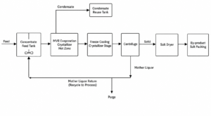
Simplified Process Flow Diagram

Pre-treatment → Pre-concentration → Evaporative concentration → Crystallization → Solids separation → Condensate recovery

Each block is sized and configured from your feed characterization — TDS, organics, hardness, chloride profile and scaling precursors.

01

Pre-treatment

pH adjustment, alkaline softening (Ca²⁺, Mg²⁺ removal), advanced oxidation for COD, and filtration to protect downstream heat exchangers from scaling and fouling.

02

Pre-concentration

High-pressure RO, softening chemistry or falling-film evaporation to lift TDS from 1–5% to 8–15% and reduce thermal duty on the evaporator.

03

Evaporative Concentration

MVR (15–25 kWh / t water) or multi-effect (0.25–0.40 t steam / t water) forced-circulation evaporation to approach saturation under controlled ΔT ≤ 10 °C.

04

Crystallization

Forced-Circulation (FC, 0.2–0.8 mm), DTB (0.5–2 mm) or OSLO (1–5 mm) crystallizer — selected by salt system, scaling risk and target crystal size.

05

Solids Separation

Pusher, peeler or scroll centrifuge with wash stage to produce handleable salt cake (> 95% solids) and clean centrate returned to the crystallizer.

06

Condensate Recovery

Condensate polishing (ion exchange or activated carbon) to reach process-water reuse specs, closing the water loop and recovering 85–95% of feed as clean condensate.

Feed Chemistry

Handling Mixed-Salt Systems

High-salinity wastewater is rarely a single salt. Process selection depends on which salts dominate, what organics are present and whether heavy metals coexist.

Wastewater TypeDominant ChemistryTypical SourceSelection NoteMaterial
NaCl brineChloride-richChlor-alkali, ion-exchange regeneration, soda plantForced-Circulation crystallizer; flat solubility requires evaporative route; titanium on wetted parts for chloride pitting resistanceTitanium (TA2)
Na₂SO₄ brineSulfate-richViscose rayon, battery by-product, textile auxDTB or FC; mirabilite / thenardite transition above 32.4 °C drives configuration and temperature windowDuplex 2205
Mixed NaCl + Na₂SO₄Eutectic systemCoal-to-chemicals, coke oven, coal gasificationSelective (fractional) crystallization operating on the NaCl–Na₂SO₄–H₂O phase diagram; eutectic point dictates achievable purity and mother-liquor purge strategyTitanium / Duplex
RO concentrateHigh TDSMembrane plant reject, cooling-tower blowdownAlready pre-concentrated (TDS 4–8%); direct forced-circulation evaporation + crystallizer chain, often MVR-driven for continuous duty316L / Duplex
Coal chemical wastewaterHigh COD + saltsCoking, coal gasification, CTL, MTOPhenol / ammonia / COD removal upstream (stripping, oxidation); FC crystallization downstream with CIP for organics foulingDuplex 2205
Pesticide / pharmaceutical brineHigh COD + tracesAgrochemical, API intermediates, fine chemicalsAdvanced oxidation (AOP) pre-treatment to break biocidal organics; FC evaporator for fouling resistance; antifoam strategy criticalTitanium / Hastelloy
Heavy-metal-bearing brineCr / Ni / As / Cu tracesElectroplating, smelting scrubber, miningHeavy-metal precipitation (sulfide / hydroxide) upstream to below discharge limit; stabilized salt output for hazardous landfill or recoverySpecialty alloys

Typical mapping only — final material and configuration selection depends on feed characterization (full ionic profile, organics, hardness) and site utility conditions.

Equipment

Core Equipment for ZLD Systems

Three equipment families carry most of the ZLD duty. Each is configured around your feed composition, not selected from a catalog.

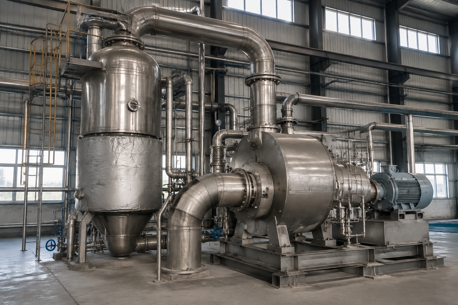
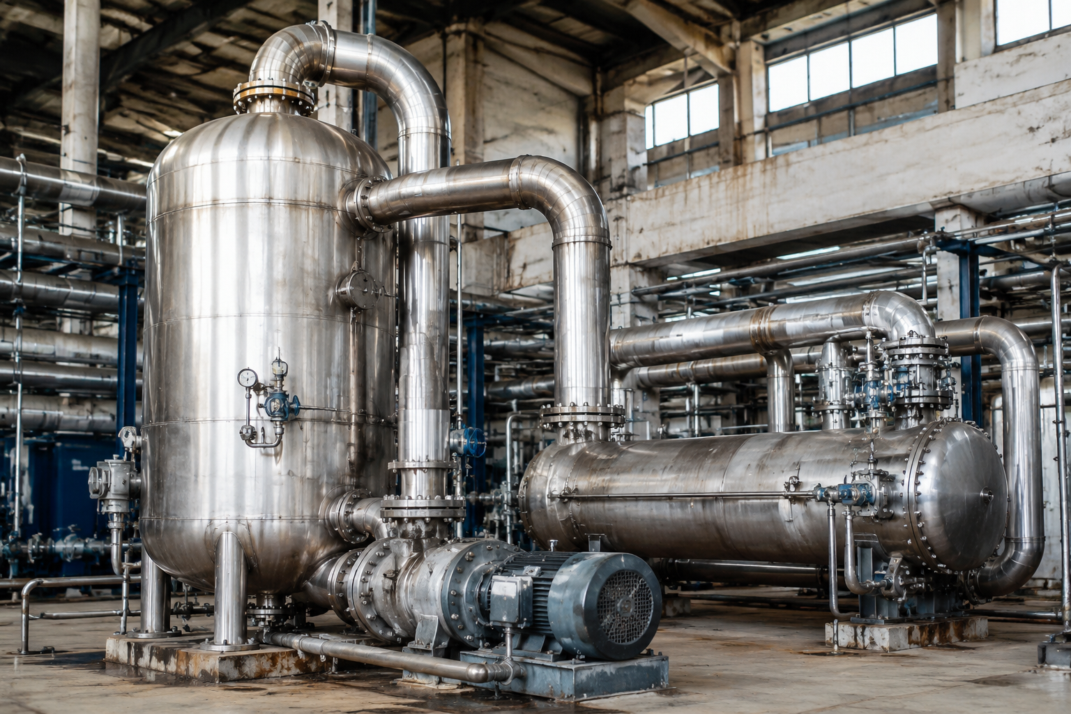
MVR evaporator system with mechanical vapor recompression compressor

MVR Evaporator

Mechanical vapor recompression upgrades secondary vapor via a single- or two-stage compressor, raising saturation temperature by 8–15 °C for reuse as heating steam.

  • Best for: continuous-duty ZLD with electricity available
  • Forced-circulation evaporator body for scaling feeds
  • Compression ratio sized to BPE of feed
15–25 kWh/twater evaporated, typical MVR duty on low-BPE brine — against 0.25–0.40 t steam / t water for triple-effect; depends on feed TDS, boiling-point rise and utility prices
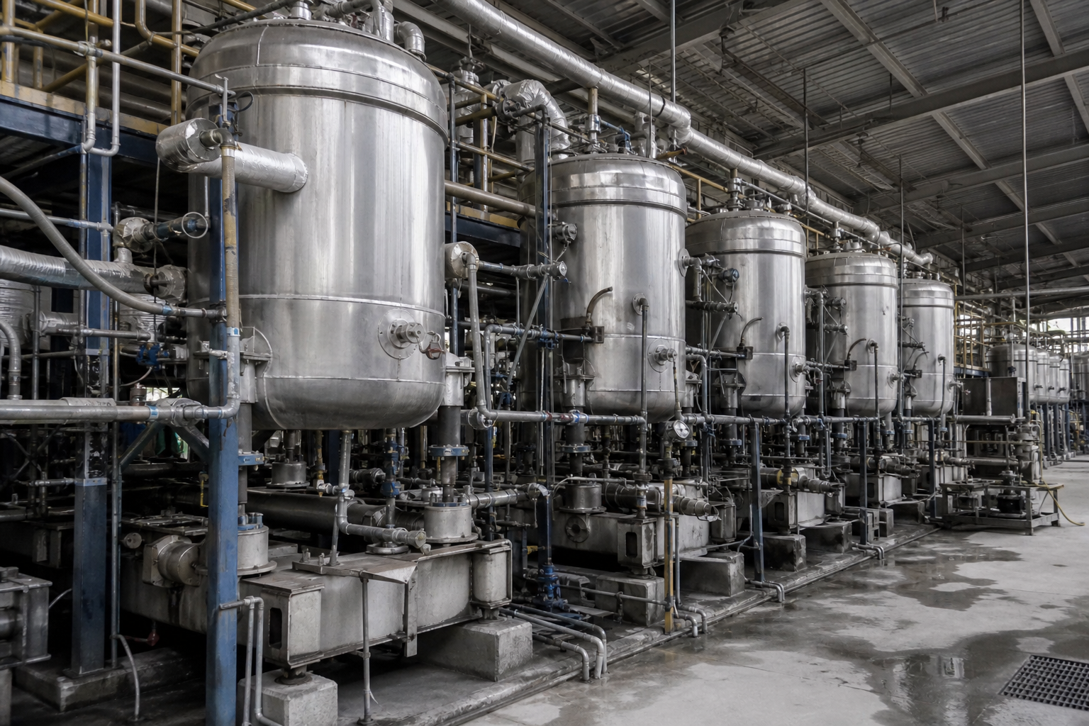
Forced-circulation crystallizer with external heater and circulation pump

Forced-Circulation (FC) Crystallizer

External circulation pump maintains tube velocity to suppress wall scaling; ΔT across the heater kept low to avoid tube-wall nucleation. Engineering reliability priority for high-TDS, high-COD and mixed-salt ZLD.

  • Best for: scaling, fouling, mixed-salt, high-TDS feeds
  • Stable under feed composition swings
  • Crystal size typically 0.2–0.8 mm
2–3 m/stube circulation velocity with heater ΔT ≤ 10 °C — set by the scaling tendency of the salt system, verified in bench testing
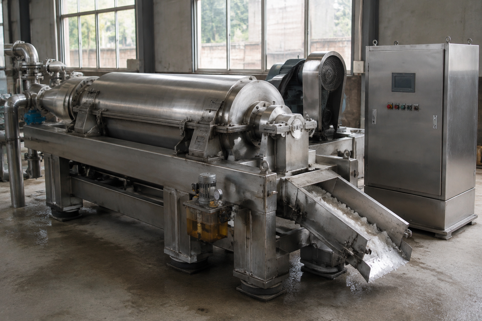
Horizontal pusher centrifuge for continuous salt dewatering

Centrifuge & Solids Handling

Pusher centrifuge for continuous NaCl / Na₂SO₄ duty; peeler or scroll centrifuge for batch or fine crystals. Wash stage reduces mother-liquor entrainment; integrated dryer (fluid-bed or conical) produces handleable salt cake.

  • Continuous pusher for large tonnage salt
  • Wash liquor designed to protect product purity
  • Dryer integration when downstream storage requires
> 95% solidshandleable salt cake after wash and dryer integration — depends on crystal morphology and wash-liquor design
Interactive Screening

Quick ZLD Screening

Enter your key wastewater parameters to receive a preliminary process route recommendation. Output is indicative only — actual selection requires laboratory solubility and impurity profiling.

T1

Evaporation Duty Estimator

Estimate the evaporation duty required to concentrate your feed to the target solids content.

Indicative Output
  • Estimated water to evaporate: — t/h
  • Concentration ratio: — ×
  • Indicative MVR specific energy: — kWh/t water
  • Indicative multi-effect steam: — t steam / t water
T2

MVR vs. Multi-Effect Energy Comparison

Compare indicative energy economics of MVR and multi-effect evaporation routes for your site utility context.

ParameterMVRTriple-Effect
Primary energy sourceElectricity (compressor duty)Steam (live steam to Effect 1)
Specific consumption (indicative)15–25 kWh / t water0.25–0.40 t steam / t water
CapExHigher (compressor + drive + control)Lower (effect shells + vacuum system)
OpExLower where electricity < 0.08 USD/kWh and steam > 30 USD/tLower where low-pressure steam is abundant or waste
SensitivitySensitive to BPE — high-BPE feeds reduce compression gainSensitive to cooling-water temperature at the final effect
Best whenContinuous duty, stable feed, electricity availableIntermittent duty, steam available, limited electrical headroom
T5

Carbon Reduction Indicator

Indicative CO₂ reduction from switching a multi-effect ZLD system to MVR, based on grid emission factor and steam source. Site-specific audit required for verification.

Values shown are typical ranges for preliminary screening. Actual energy consumption, condensate quality and recovery rate depend on feed composition (TDS, COD, organics profile), boiling point elevation, utility conditions (steam pressure, electricity tariff, cooling-water temperature), site altitude and project-specific operating envelope. Mixed-salt separation feasibility requires laboratory solubility and impurity profiling before process guarantees can be issued. Outputs are not a process or financial guarantee.
FAQ

Frequently Asked Questions

Honest answers to the questions engineers and plant managers ask before specifying a ZLD system.

How do I know whether ZLD is necessary for my plant?+

ZLD is typically justified when one or more of the following apply: (a) discharge limits on TDS, COD, ammoniacal nitrogen or heavy metals have dropped below what biological + membrane treatment can reach; (b) the plant has a mandated water-reuse target above 80%; (c) hazardous mixed-salt disposal exceeds 200 USD/t; (d) the site has no remaining discharge outlet (inland, arid, or regulated catchment). A 30-minute feed characterization review usually tells us whether a ZLD feasibility study is justified.

What is the typical specific energy consumption of a ZLD system?+

MVR-based ZLD evaporators typically consume 15–25 kWh per ton of water evaporated for low-BPE feeds (NaCl brine at moderate concentration), rising to 30–40 kWh/t at high BPE or for high-TDS feeds approaching saturation. Triple-effect systems consume 0.25–0.40 t steam per ton of water. The exact figure requires a heat-and-mass balance on your feed at target concentration — BPE, latent heat and compression ratio are the dominant variables.

Can mixed salts be separated into sellable products?+

Selective crystallization of NaCl and Na₂SO₄ is technically feasible when the feed sits in a workable region of the NaCl–Na₂SO₄–H₂O phase diagram at 25–100 °C. Achievable purity is typically 95–99% for the first salt, bounded by the eutectic composition and by trace organics and heavy metals. Sellable grade requires washing and centrate management — sellability is set by your offtake spec, not just by the crystallizer. Mixed-salt separation requires laboratory solubility and impurity profiling before any purity guarantee can be issued.

How do you handle foaming and scaling in high-COD brines?+

High-COD brines (pesticide, pharmaceutical, coal-chemical) commonly foam and scale because dissolved organics act as surfactants and because Ca²⁺ / Mg²⁺ / sulfate combinations exceed solubility during concentration. Mitigation combines (a) advanced oxidation (ozone, Fenton, electrochemical) to break biocidal and surface-active organics upstream, (b) softening to remove Ca²⁺ / Mg²⁺, (c) forced-circulation evaporators at 2–3 m/s tube velocity with ΔT ≤ 10 °C, (d) antifoam dosing controlled by level-sensor feedback, and (e) CIP cycles tuned to the fouling deposit (alkaline boil-out for organics, acid wash for carbonate / sulfate scale). The specific combination is driven by COD/TDS ratio, surfactant load and hardness profile.

How is the optimal number of effects chosen?+

The optimal number of effects is the result of a lifecycle-cost trade-off: each additional effect reduces steam consumption by approximately 1/n of the single-effect value (a 3-effect uses roughly 0.4 t steam / t water, a 4-effect roughly 0.3), but adds capital (effect shell, separator, pump, interconnecting piping) and increases total heat-transfer surface area. For most industrial wastewater ZLD applications, 3 effects provide the best lifecycle cost when steam is priced 25–40 USD/t; MVR typically beats 4+ effects once electricity is below 0.08 USD/kWh. The crossover is project-specific and requires a sensitivity analysis on utility prices and operating hours.

Ready to Engineer Your ZLD System?

Send us your wastewater characterization (TDS, COD, main salts, hardness, organics profile, throughput) and site utilities (steam pressure, electricity tariff, cooling water). We will respond with a process route recommendation, indicative sizing and lifecycle-cost comparison within 2 business days.

Request a Proposal

Send your feed characterization (TDS, COD, main salts, viscosity), throughput and product targets — we respond with a preliminary process route within two business days.