Evaporation systems need automation because they couple heat transfer, vapour-liquid separation, crystallization, and compression into one tightly interacting process: a small drift in vacuum, feed concentration, or compressor load propagates within minutes into higher energy consumption, off-spec product, salt blockage, or trips. Modern practice answers this with a layered closed-loop architecture — sense, compute, act, protect — in which an MVR compressor is modulated to keep its vapour temperature rise inside a 5-20°C window, and multi-variable PI control replaces independent single loops that fight each other. This guide explains the control architecture, the key measured variables, the seven control indicators every multi-effect operator tracks, and why the humble globe valve turns out to be the most important final control element in the plant.
Why Manual Operation Fails in Evaporation Plants
An evaporator is a multi-variable, strongly coupled system. Raising first-effect steam pressure increases evaporation rate but drops last-effect vacuum; a feed-concentration upset changes boiling-point elevation, which shifts the compressor’s operating point; crystal growth depends on supersaturation, which responds to both temperature and circulation rate. Single-loop controllers that treat each variable independently cannot coordinate these interactions, and manual operation reacts only after quality or energy metrics have already moved. Automation attacks the problem at four levels simultaneously — measurement, model, actuation, and protection.
The Four-Module Closed-Loop Control Architecture
Module 1: Data Acquisition
High-accuracy instruments capture the evaporation subsystem’s temperatures, pressures, compressor speed, and feed flow, and the crystallization subsystem’s supersaturation (inferred), slurry density, and mother-liquor pH. Raw signals are filtered and normalized into a consistent data vector before any control action is derived from them — noisy density or conductivity signals are the classic source of control hunting in salt plants.
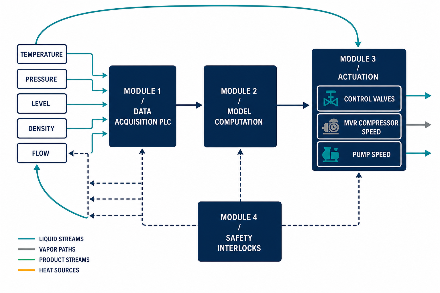
Module 2: Model Computation
The controller layer ranges from classical multi-variable PI schemes — which adjust several actuators together instead of one at a time — to advanced implementations that use process models or machine-learning predictors trained on operating history to anticipate behaviour several time-steps ahead. The optimization objective is explicitly multi-dimensional: energy cost, product purity, and equipment load are balanced rather than traded by operator intuition.
Module 3: Actuation
Computed setpoints are issued as standard industrial signals (4-20 mA) to the compressor variable-frequency drive, feed control valves, discharge valves, and slurry circulation pumps. This is where the architecture meets hardware — and where valve selection determines how much of the computed control action actually reaches the process.
Module 4: Safety and Interlocks
A protection layer watches operating boundaries continuously: over-temperature, over-pressure, abnormal liquid level, compressor surge, and vibration each trigger alarms or interlocked shutdowns. Every final element carries a defined failure position (fail-open or fail-closed) chosen so that a signal or air loss leaves the plant in a safe state — for example, a feed valve that fails closed on loss of signal while the compressor trips on low flow.
Condensed to a procurement-grade checklist, the four modules map to hardware and selection criteria as follows:
| Module | Typical hardware | Selection basis |
|---|---|---|
| Data acquisition | Resistance thermometers, pressure transmitters, flow meters, slurry density (Coriolis or nuclear gauge), conductivity and pH probes, compressor vibration sensors | Accuracy and drift specs against the control band; inferred variables (density, conductivity) validated on the actual liquor |
| Model computation | Compact PLC for single-train duties; DCS for multi-train plants; optional advanced-control server | I/O and loop count, scan rate, and whether the energy stake justifies a model-predictive layer |
| Actuation | Compressor variable-frequency drive, feed and discharge control valves, slurry circulation pump drives | Valve rangeability (50:1–100:1) and authority (30–70% of system pressure drop at design flow), as detailed below |
| Safety and interlocks | Hardwired trip relays, emergency shutdown layer, anti-surge valve, vibration and temperature trips | Independence from the basic control layer; every final element with a defined fail position |
Key Measured Variables in MVR Plants
Two variable groups matter most. On the evaporation side: heating-zone and vapour temperatures, separator and system pressures, compressor rotational speed and differential, and feed flow. On the crystallization side: mother-liquor supersaturation (usually inferred from density and temperature), slurry density, and mother-liquor pH. MVR-specific control logic keeps the secondary-vapour compression temperature rise inside roughly 5-20°C — enough driving force for efficient heat transfer, without wasting compressor power on excessive lift. Equipment suppliers report thermal efficiency maintained above 90% when this window and the associated balances are held; treat such figures as design-dependent rather than guaranteed.
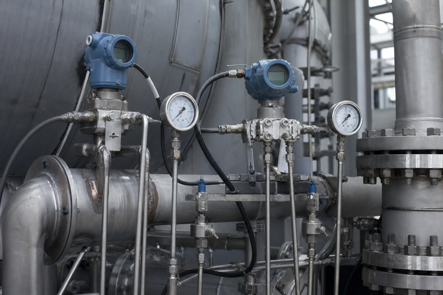
Three dynamic couplings do most of the day-to-day work in an MVR evaporator. Compressor speed follows the temperature gradient and stage pressures. Feed-versus-level control adjusts feed flow and circulation-pump speed as concentrate viscosity and concentration change, keeping high tube velocity to prevent crystallization deposits, while the discharge valve holds vessel level. Supersaturation control in the crystallizer modulates cooling rate and slurry circulation rate so that crystal growth stays steady — uncontrolled supersaturation produces nucleation bursts, fine uneven crystals, and poor salt purity in crystallization duty.
The Seven Control Indicators of Multi-Effect Evaporators
Multi-effect trains have a standard indicator set that operators scan in exactly the same order every shift. Each indicator has a defined “if abnormal, check this” logic, summarized below.
| Control indicator | Why it matters | Diagnostic direction when abnormal |
|---|---|---|
| Live-steam superheat | Excess superheat reduces first-effect heat transfer | Inject water to desuperheat — saturated steam transfers heat better despite lower pressure |
| Live-steam pressure | Main evaporation driving force | Keep within design band; higher pressure = faster evaporation but watch downstream effects |
| Last-effect vacuum | With first-effect pressure, sets total temperature driving force; normally below about −0.08 MPa (gauge) | Vacuum drop: check condenser fouling, cooling-water flow, and cooling-water temperature |
| Effect liquid levels | Stable levels prevent tube-section scaling | Check feed/discharge valves and level transmitter |
| Effect temperatures | Inter-effect ΔT minus boiling-point elevation = that effect’s driving force | A suddenly large ΔT means falling heat-transfer efficiency: check fouling both sides, blockage, trap function, vapour-line restrictions |
| Effect differential pressures | Mirror of the temperature picture | Rising ΔP across one effect signals blockage or fouling on that effect |
| Specific steam consumption | The headline energy metric | Stable process should hold it stable — see the counter-intuitive case below |
Two Counter-Intuitive Diagnostic Rules
Falling steam consumption is not always good news. If specific steam consumption drops noticeably while nothing else improved, suspect inter-effect vapour bypassing — typically leakage in a condensate drain line of one of the effect heaters, or a non-condensable blowdown valve opened too far. The steam appears “saved” but is shortcutting the train and destroying the temperature ladder.
Last-effect vacuum falling while first-effect pressure rises can be normal. When first-effect steam pressure is deliberately raised, evaporation rate increases, more vapour reaches the final condenser, and last-effect vacuum falls as a consequence of higher load — not because the condenser has failed. Conversely, a vacuum drop with unchanged steam supply is a genuine condenser-side fault. Distinguishing load-driven from fault-driven vacuum movement is one of the habits that separates experienced operators from alarm-chasers; continuous automation does the same discrimination with pressure-trend logic.
PLCs, DCSs, and SCADA: Who Does What
In a typical evaporation-plant control hierarchy, a PLC (or a DCS controller in larger plants) executes the regulatory and interlock layer — PID loops, sequential start/stop logic, safety interlocks — at millisecond cadence. The DCS or SCADA layer aggregates those controllers into an operating picture: historian trends, alarm management, energy dashboards, and remote access. The practical division of labour: anything that must react fast or fail safe lives in the controller; anything that supports decisions and reporting lives one level up. Modern supervisory layers add early-warning functions — for example, tracking heat-transfer-coefficient decay to predict cleaning needs before pressure or quality drifts, a technique detailed further in the energy efficiency and steam economy guide.
Compressor Protection: Anti-Surge and Sequential Start/Stop
The MVR compressor is the single most expensive rotating machine in the plant, and its protection defines a whole sub-system of control logic. Anti-surge control continuously compares operating flow against the surge line for the current speed and inlet conditions, and opens a vapour recycle or bypass valve before the machine enters surge — the flow-reversal condition that damages bearings and blades within seconds. Sequential start logic typically runs: preheat the circuit with a small steam trim, establish circulation flow, evacuate non-condensables, roll the compressor to minimum speed, then ramp load while watching vibration and differential. Sequential stop reverses the ramp and, on trips, drives valves to their engineered failure positions. Getting this sequence right is what allows a plant to ride through upsets instead of flooding separators or crashing the compressor.
The Globe Valve: Final Control Element of the MVR Plant
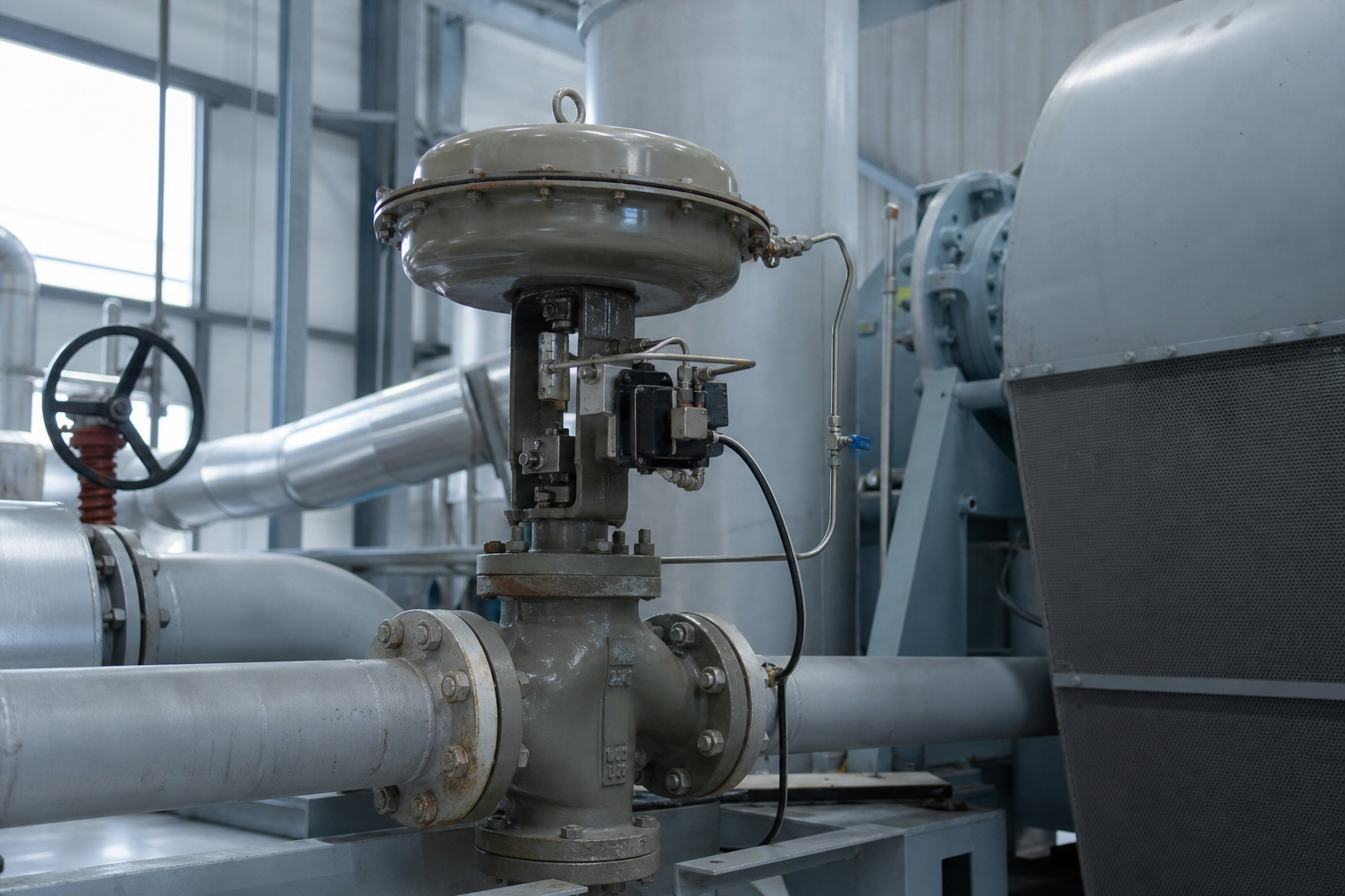
Regulatory control ultimately arrives at valves, and in MVR service the linear-motion globe valve dominates because of its precise throttling and predictable flow characteristic. Its trim — the plug, seat, and cage geometry — determines how flow relates to travel, in one of three standard characteristics: linear (flow proportional to travel), equal-percentage (each increment of travel changes flow by the same percentage — suited to wide-range, nonlinear processes and the usual choice for MVR feed valves), and quick-opening (large flow at small travel, for on/off duty).
| Installation point in MVR system | Control duty | Notes |
|---|---|---|
| Feed flow control | Matches feed to evaporation capacity; holds level and concentration | Equal-percentage trim typical |
| Forced-circulation loop | Circulation rate and tube velocity | Anti-scaling duty; high cycle count |
| Vapour bypass / throttle | Start-up, part load, anti-surge protection | Protects the compressor — fast-acting |
| Concentrate discharge | Discharge of concentrate / slurry | Erosion service with crystals |
| Non-condensable blowdown | Vacuum preservation, inert removal | Over-opening mimics leakage |
| Make-up and auxiliary streams | Desuperheating water, flush, CIP routing | Often small forged-body valves |
Sizing and selection rules are concrete: calculate Cv/Kv at full and minimum load; require a rangeability of roughly 50:1 to 100:1 for modulating duty; allocate the valve about 30-70% of total system pressure drop so it actually has authority over the process (too little and the loop cannot control; too much and pumping energy is wasted); specify cavitation-resistant multi-stage trims for high-differential services; and always define the failure position to match process safety. Finally, remember the system view: a valve must never throttle a pump into an unstable region or push a compressor toward surge — valve, pump, and compressor are one control chain, a dependency covered from the design side in process flow design for evaporation plants.
When This Route May Not Fit
Not every evaporation plant needs the full closed-loop stack. A single-effect, small-capacity unit on a simple duty is well served by a compact PLC with a handful of single loops; a multi-variable architecture would buy precision the process cannot use. Older multi-effect plants without mechanical vapor recompression carry no compressor train—and with it no surge control, compression-ratio logic or anti-surge valve to justify the protection layer’s cost. And a site whose instrument-maintenance capability is thin—no technician who can calibrate density or conductivity instruments and diagnose loop hunting—will find high automation turning from an asset into a liability: loops left in manual, alarms suppressed, the plant quietly run by operator habit again. The architecture pays where the energy stake and the equipment complexity are both real.
What Must Be Verified
Five deliverables close out a control-system scope:
- Control point list. A complete I/O schedule—every measured variable, actuator, alarm and interlock point, mapped to its instrument tag.
- Interlock and fail-position test plan. A factory- and site-acceptance test outline exercising every trip and verifying the defined fail position of each final element under signal and air loss.
- Compressor surge-line data. The vendor’s surge curve for the actual machine, with anti-surge margin and control response tuned against it—not against a family curve.
- Inferred-variable validation. Density- and conductivity-based inference of concentration and supersaturation, checked against lab samples on the actual liquor at both startup and end-of-run concentrations.
- Post-commissioning efficiency baseline. Measured steam economy or specific energy consumption in the first month of stable operation, so later drift is detected against a baseline rather than argued about.
Frequently Asked Questions
What is the most important controlled variable in an MVR evaporator?
The compressor’s vapour temperature rise, normally held inside roughly 5-20°C. It couples energy consumption, heat-transfer driving force, and compressor load in one number, and holding it stable while feed conditions drift is the central task of the control system.
Why did our multi-effect evaporator’s steam consumption fall while capacity dropped?
Suspect inter-effect vapour bypassing — leaking condensate drains or an over-open non-condensable valve. Steam that shortcuts the train lowers measured consumption while destroying the temperature ladder, so treat a sudden “improvement” in specific steam consumption as a fault signal, not a win.
Why does last-effect vacuum drop when first-effect steam pressure is raised?
Because evaporation rate rises, more vapour reaches the final condenser, and vacuum falls with load. This is normal load-following behaviour. A vacuum drop with unchanged steam supply, by contrast, points to condenser fouling, insufficient cooling water, or warm cooling water.
Why are equal-percentage control valves preferred for MVR feed control?
Because the process gain of an evaporator changes with load, and the equal-percentage characteristic compensates for it, keeping the total loop gain roughly constant across the range. Linear trim suits level loops with near-constant gain; quick-opening trim suits open/close duty only.
How is supersaturation controlled in evaporative crystallizers?
By modulating cooling rate and slurry circulation rate to keep supersaturation in the metastable growth zone. Held steady, crystals grow uniformly; allowed to spike, the liquor nucleates explosively and produces fine, uneven crystals that are hard to dewater and wash.